PS288_PS388_PS588_981-0424-002D - 第150页
Maintenance ■ Workspace, Head and Gantry 4—10 Data I/O • 981-0424 -002 back 2. Adjust the down speed— 2a. Open the safety door nearest the PNP head and locate the in-line air flow control for the upper end of the air cyl…
■ Workspace, Head and Gantry ◘ Socket Adapters and Actuation
PS Series Owner’s Manual 4—9
back
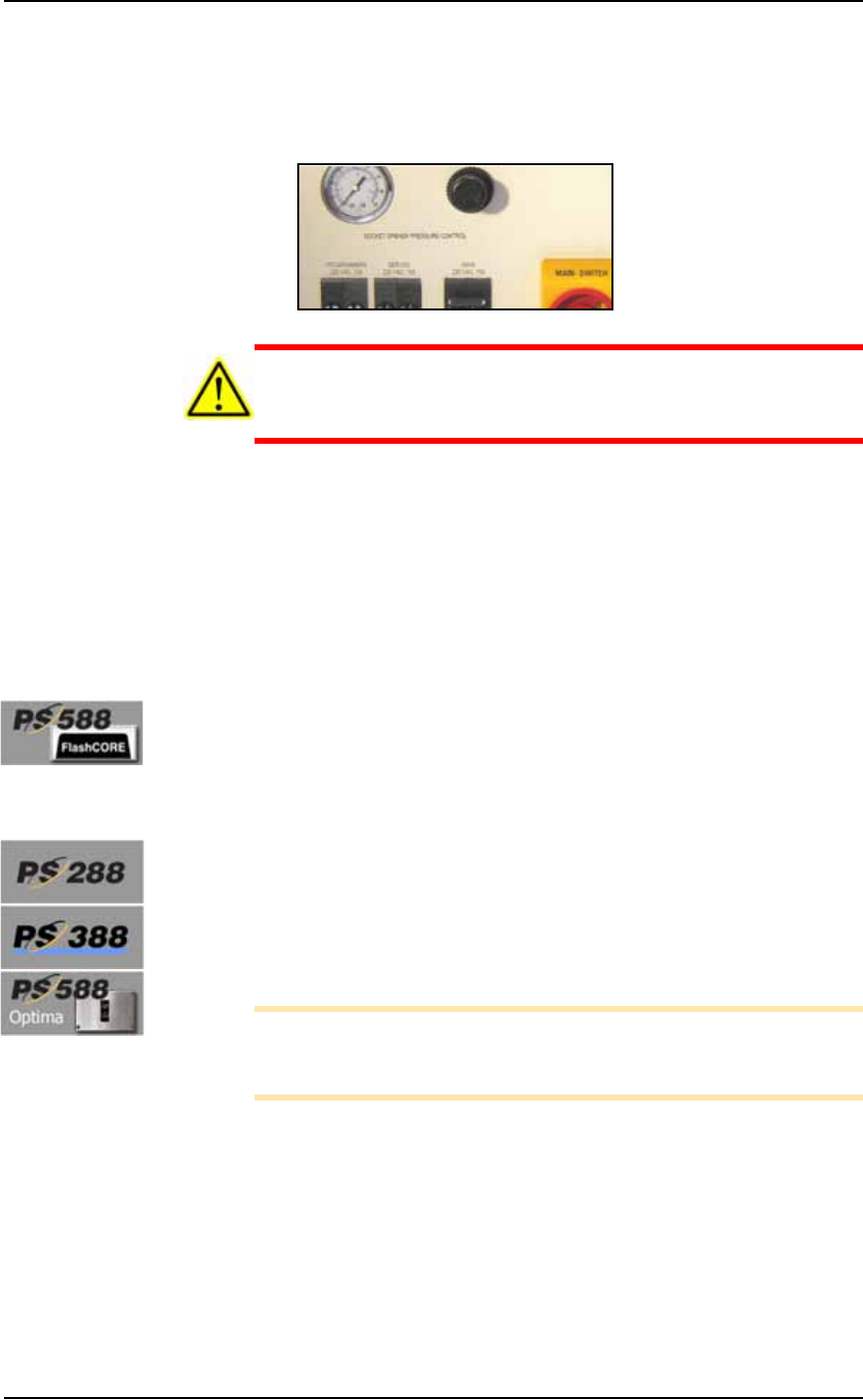
2. Power Panel—
2a. Verify that the Socket Actuator pressure regulator (on the back
Power Panel) is set within this range:
• Standard Sockets, 1.3 ±.34 Bar (20 ±5 PSI), and for
• HIC sockets, 2.2 ±.55 Bar (32 ±8 PSI).
CAUTION: Possible excessive socket wear. Setting the Socket
Actuator air pressure too high can cause premature wear of the
sockets.
2b. If experiencing problems, increase the Socket Opener air pres-
sure slightly to the high end of the range.
2c. Open and close the socket to check that it opens with one stroke
of the opener.
3. Restart Job—
3a. Restart the job and check the action of the Socket Opener and the
pick and place performance.
Pressure for Actuators on the Programmers, PS588
[PS588 Machines with FlashCORE] Actuators are part of the pro-
grammer. If Socket Actuators are moving too fast or too slowly, or
you are experiencing pick or place problems, contact Data I/O sup-
port or a qualified technician.
Adjusting the Socket Opener Speed
Prior to adjusting the actuator speed, the actuator pressure should be
set (see the previous heading).
Speed for Openers on the PNP Head
[PS288, PS388 and Optima Programmers only on PS588]
Note: Prior to adjusting the opener speed, the opener ribs must be
adjusted for the current socket. If this has not been done, see Adjust
Socket Opener Ribs on page 3-41.
To adjust the Socket Opener speed:
1. Preparation—
1a. Ensure that power and air are connected and ON, and a Socket
Adapter is installed.
1b. At the Gantry Window, click the label for a programmer with
easy access. The head will stop over socket 1.
Maintenance ■ Workspace, Head and Gantry
4—10 Data I/O • 981-0424-002
back
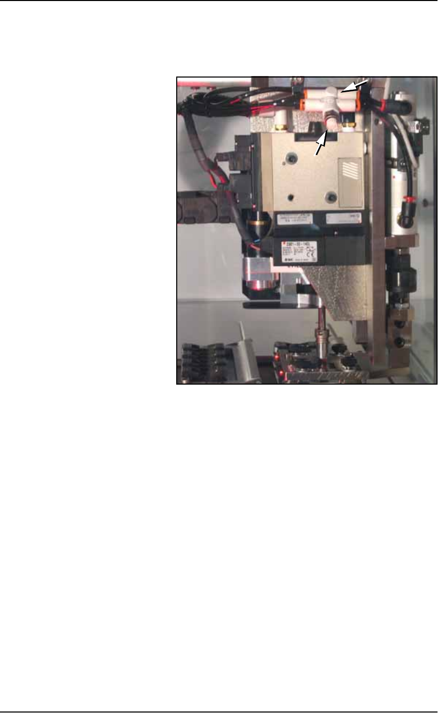
2. Adjust the down speed—
2a. Open the safety door nearest the PNP head and locate the in-line
air flow control for the upper end of the air cylinder on the head.
See figure below.
Figure 4-6: Flow controls for the Socket Opener Speed control. (PS288,
PS388 and Optima only on PS588.) (Your head assembly may not look
like this one.)
2b. Loosen the locking ring and adjust the down flow control as 1/2
to 1 revolution clockwise for slower or counter-clockwise for
faster.
2c. Close the Safety Door, and clear the Safety Door warning on the
monitor.
2d. At the Actuate tab of the Gantry Window, click the Actuate
Socket toggle switch to ON while listening and watching the
opener.
If it is too fast it will produce a louder thump than optimum
when it opens the socket.
If it is too slow it will look slow.
2e. Click Actuate Socket OFF.
2f. Adjust the flow control as necessary and repeat the test.
2g. Tighten the locking ring when done.
3. Adjust the up speed—
3a. Follow the same procedure as above with the other flow control.
■ Workspace, Head and Gantry ◘ Cleaning the PS Machine
PS Series Owner’s Manual 4—11
back
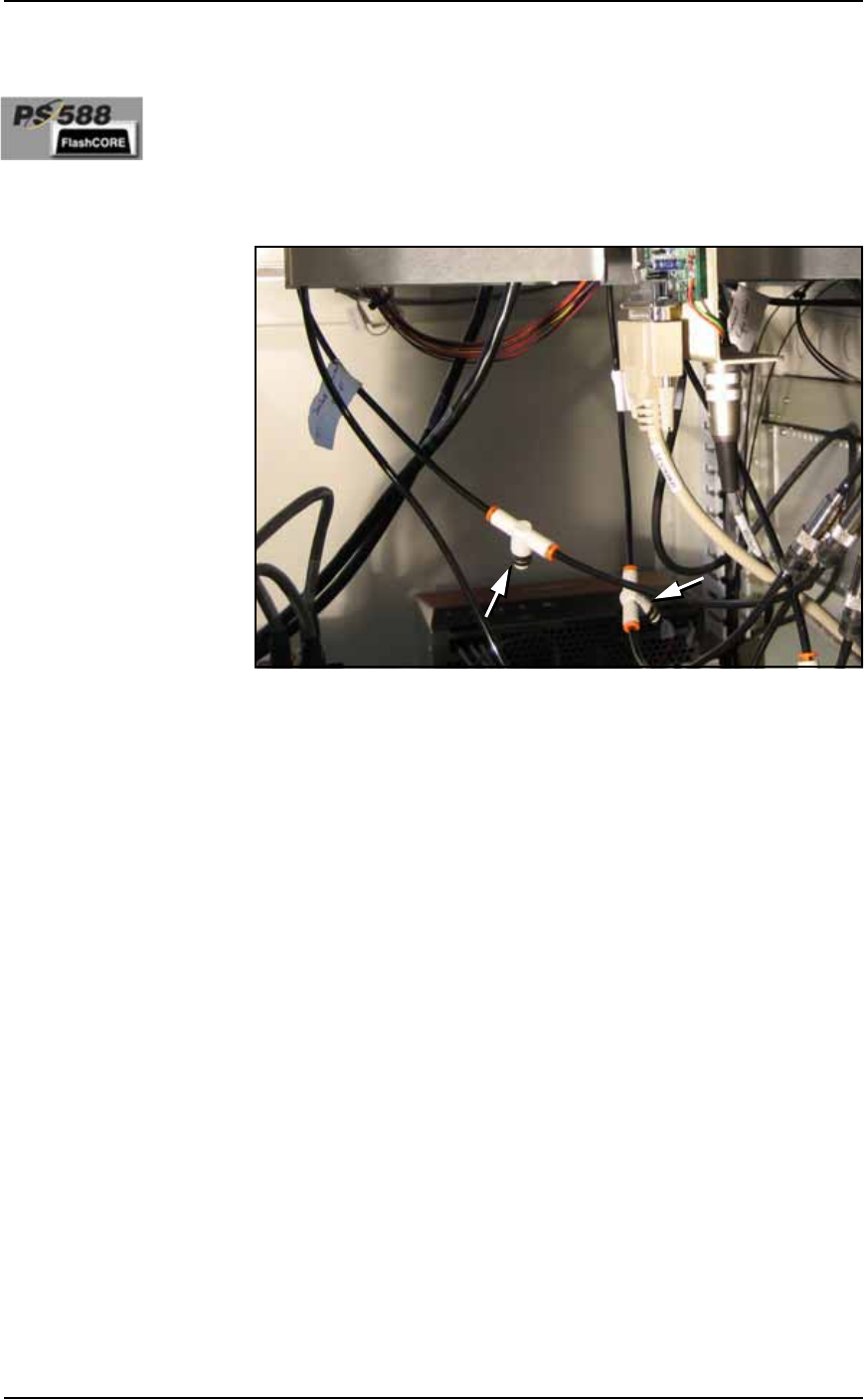
Adjusting the Socket Actuator Speed on PS588
Programmers
[PS588 Machines with FlashCORE]
To adjust the speed of the Actuators on the PS588 with actuators on
the programmers, perform the same procedure as above, with the fol-
lowing differences:
The flow controls are located inside the cabinet in some models. If
your PS588 doesn’t have flow controls, contact Data I/O.
Figure 4-7: Actuator flow controls on PS588.
Cleaning the PS Machine
General Machine Cleaning
General cleaning should be performed on a weekly basis. General
cleaning includes but is not limited to the following:
1. Remove all dropped devices, debris, and other materials from all
working areas.
2. With air and power OFF or disconnected, remove all devices and
materials that may have fallen inside the machine.
3. Use dry, compressed air to remove all dust and debris from the
work surface and from under the machine.
4. Dust the safety shields, inside and outside, with an antistatic
cleaner.
5. Wipe the top and side panels to remove grease, fingerprints, and
dust.
6. Dust the top surfaces of the input/output modules.
Cleaning the Vision Camera Lens