PS288_PS388_PS588_981-0424-002D - 第153页
■ Workspace, Head and Gantry ◘ Adjusting Prob e Blow-Off Pressure PS Series Owner’s Manual 4—13 back 2. Pull off the breakaw ay stem an d check the O-ring. Replace if necessary . 3. Reassemble. Cleaning the Probe T ip T …
Maintenance ■ Workspace, Head and Gantry
4—12 Data I/O • 981-0424-002
back
WARNING: Vision hazard. Always use care and wear protective
eye goggles when cleaning with pressurized air. Pressurized air or
debris blown into the eyes or skin could cause bodily damage.
1. Use dry compressed air to remove all dust and other foreign
material from the camera lens.
2. Shut off power to the PS Machine. For more information see
Turning Off the System on page 4-4.
WARNING: Electrocution hazard! Turn off the main power switch
before opening any cabinet doors or removing any panels. Servic-
ing the PS Machine involves a risk of electric shock if warnings are
not followed.
3. Open the right side access door and clean the lens using a lens
soft cloth or lens cleaning tissue. If desired, dampened material
with isopropyl alcohol.
PNP Probe
The workspace PNP head has a Probe which requires periodic main-
tenance. The headings below describe maintenance for this Probe, as
well as for the PNP head Probe on the optional Tape Output Module
if this has been installed.
Checking the Probe Tip
Worn or damaged probe tips on the PNP head or on the Tape Output
PNP head (if installed) can cause dropped devices and placement
problems.
1. Check the rubber probe tips for cracks or tears in the rubber. If
necessary, replace with a probe tip of the same size.
2. Test the probe tip—
2a. At the Setup window, click System > Gantry.
2b. Click the Vacuum switch to ON.
2c. Push the E-Stop.
2d. Place a device on the target probe.
2e. If the vacuum does not firmly hold the device, replace the probe
tip with a probe tip of the same size.
Checking the Probe Assembly
(2009 and newer models)
Check that it is not loose. Tighten the set screw on the breakaway
stem. If you suspect or hear an air leak:
1. Remove the set screw on the breakaway stem.
Parts of a probe tip
are:
• Steel breakaway tip
or stem
• Steel nozzle
• Rubber cup or tip
■ Workspace, Head and Gantry ◘ Adjusting Probe Blow-Off Pressure
PS Series Owner’s Manual 4—13
back
2. Pull off the breakaway stem and check the O-ring. Replace if
necessary.
3. Reassemble.
Cleaning the Probe Tip
To clean the Probe tip:
1. Move the PNP head to a convenient position by clicking one of
the yellow labels on the Gantry Window.
2. Push the E-Stop.
3. Wipe the tip with a damp cloth. (Do not use alcohols or sol-
vents.)
Note: Do not touch the probe tip. Finger oils can cause small
devices to stick.
Adjusting Probe Blow-Off Pressure
Note: The flow controls are set at the factory and should not
require adjustment. If adjustments need to be made, they should be
done in small steps until the desired results are reached.
Blow-off is a small puff of air applied at the probe during the device
drop event to assist in removing a device from the probe. Blow-off is
produced by a vacuum generator on the PNP head (and at the Tape
Output PNP head, if Tape Output is present). If set too high, blow-off
could cause device misalignment during placement.
To adjust blow-off pressure on any vacuum generator:
1. Preparation—
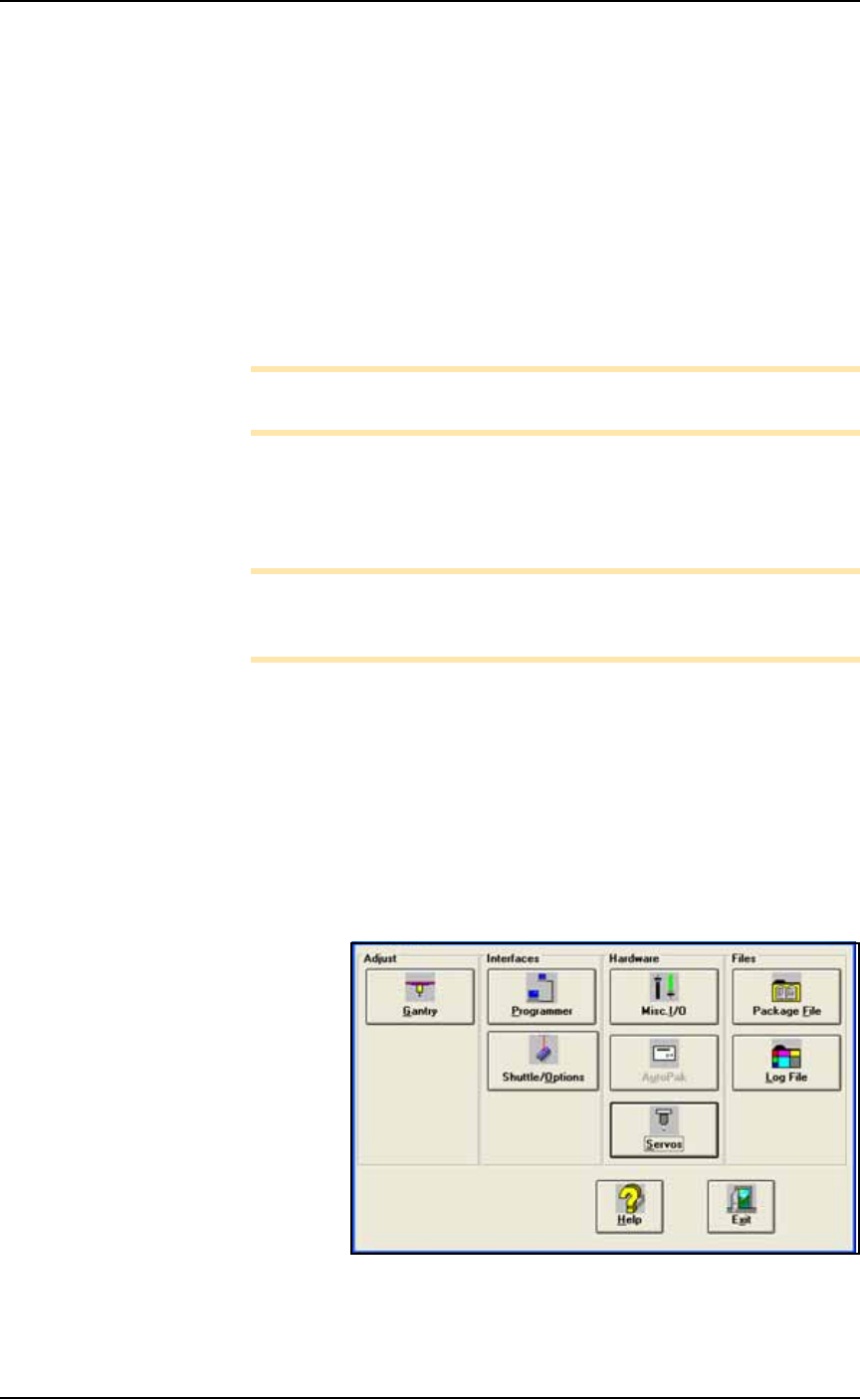
1a. At the I/O Interface Window (System > Misc. I/O), select the
desired vacuum generator.
Figure 4-8: The System Window is a menu to many subsystems
including Shuttle/Options.
Maintenance ■ Workspace, Head and Gantry
4—14 Data I/O • 981-0424-002
back
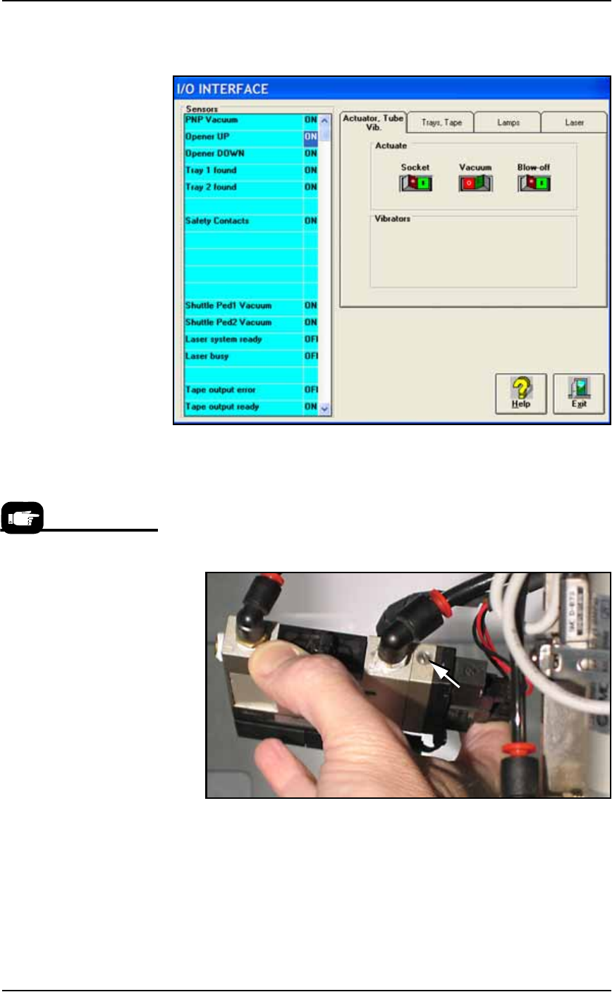
1b. Click Vacuum to the OFF position.
1c. Click Blow-off to the ON position.
Figure 4-9: Vacuum (shown OFF) and Blow-off (shown ON) on the
I/O Interface Window.
2. Vacuum generator—
2a. On top of the vacuum generator, locate the blow-off adjustment
screw above the valve coils (where the wires plug in). See Figure
4-10. The vacuum generator block at the main PNP head will
need to be removed for access.
Figure 4-10: The Blow-off adjustment screw on PNP head vacuum
generator.
3. Adjust—
3a. Turn the adjustment screw in fully clockwise. This blocks all air
and there is no blow-off (puff of air) at the PNP probe.
3b. Turn the adjustment screw 1/2 turn counterclockwise.
For instructions to remove the
Vacuum Generator at the
main PNP head see Vacuum
Generator Filters and Silenc-
ers on page 4-15.