PS288_PS388_PS588_981-0424-002D - 第154页
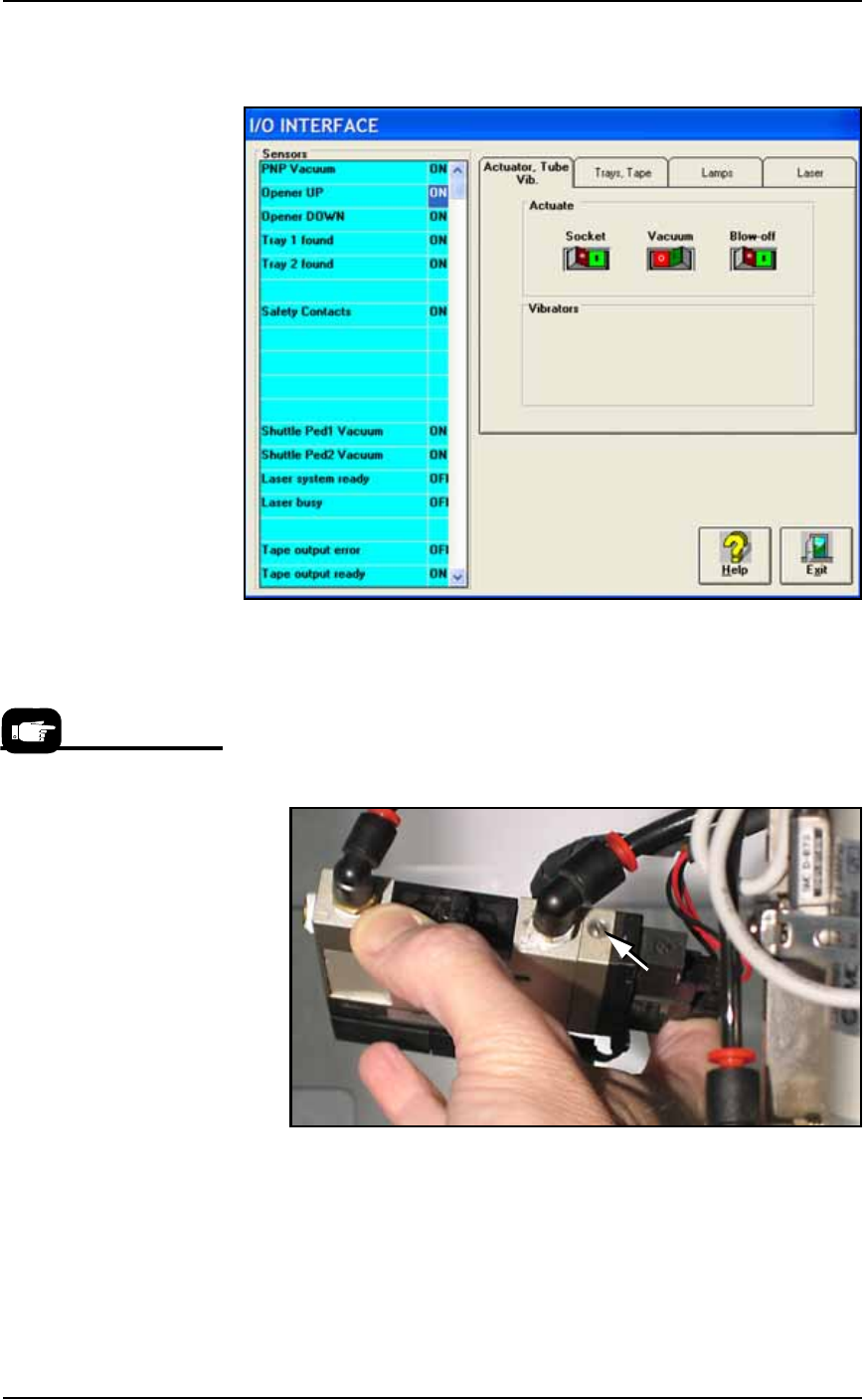
Maintenance ■ Workspace, Head and Gantry 4—14 Data I/O • 981-0424 -002 back 1b. Click V acuum to the OFF position. 1c. Click Blow-of f to the ON position. Figure 4-9: V acuum (shown OFF) and Blow -off (shown ON) on the I…
■ Workspace, Head and Gantry ◘ Adjusting Probe Blow-Off Pressure
PS Series Owner’s Manual 4—13
back
2. Pull off the breakaway stem and check the O-ring. Replace if
necessary.
3. Reassemble.
Cleaning the Probe Tip
To clean the Probe tip:
1. Move the PNP head to a convenient position by clicking one of
the yellow labels on the Gantry Window.
2. Push the E-Stop.
3. Wipe the tip with a damp cloth. (Do not use alcohols or sol-
vents.)
Note: Do not touch the probe tip. Finger oils can cause small
devices to stick.
Adjusting Probe Blow-Off Pressure
Note: The flow controls are set at the factory and should not
require adjustment. If adjustments need to be made, they should be
done in small steps until the desired results are reached.
Blow-off is a small puff of air applied at the probe during the device
drop event to assist in removing a device from the probe. Blow-off is
produced by a vacuum generator on the PNP head (and at the Tape
Output PNP head, if Tape Output is present). If set too high, blow-off
could cause device misalignment during placement.
To adjust blow-off pressure on any vacuum generator:
1. Preparation—
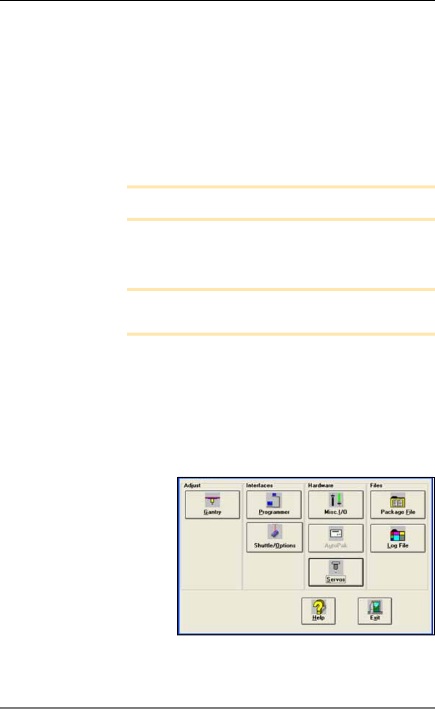
1a. At the I/O Interface Window (System > Misc. I/O), select the
desired vacuum generator.
Figure 4-8: The System Window is a menu to many subsystems
including Shuttle/Options.
Maintenance ■ Workspace, Head and Gantry
4—14 Data I/O • 981-0424-002
back
1b. Click Vacuum to the OFF position.
1c. Click Blow-off to the ON position.
Figure 4-9: Vacuum (shown OFF) and Blow-off (shown ON) on the
I/O Interface Window.
2. Vacuum generator—
2a. On top of the vacuum generator, locate the blow-off adjustment
screw above the valve coils (where the wires plug in). See Figure
4-10. The vacuum generator block at the main PNP head will
need to be removed for access.
Figure 4-10: The Blow-off adjustment screw on PNP head vacuum
generator.
3. Adjust—
3a. Turn the adjustment screw in fully clockwise. This blocks all air
and there is no blow-off (puff of air) at the PNP probe.
3b. Turn the adjustment screw 1/2 turn counterclockwise.
For instructions to remove the
Vacuum Generator at the
main PNP head see Vacuum
Generator Filters and Silenc-
ers on page 4-15.
■ Workspace, Head and Gantry ◘ Checking the Automatic Tray Feeder
PS Series Owner’s Manual 4—15
back
Checking the Automatic Tray Feeder
[TF20 Tray Feeder only]
1. Stop or Pause a job if one is running.
2. Check the automatic Tray Feeder for damaged or broken parts
and replace as necessary.
3. Visually inspect the conveyor belts for dirt, nicks, or other signs
of damage.
4. If the conveyor belts are dirty, clean with dry, compressed air
and wipe with a dry, lint-free cloth and isopropyl alcohol.
5. Check the urethane pinch roller attached to the tray clamping
mechanism for signs of wear or damage. Replace as necessary.
Clean with a dry, lint-free cloth and isopropyl alcohol.
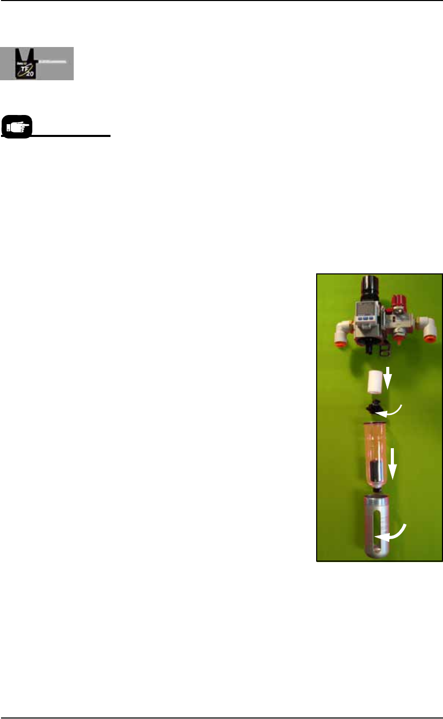
Replacing the Input Air Filter
1. Shut off shop air and disconnect the input air line from the Air
Filter/Regulator.
2. Unscrew the air contamination col-
lection bowl housing.
3. Pull off the clear collection bowl.
Clean out any dirt, oil, or water.
4. Unscrew the black knob below the
filter.
5. Pull off the filter. Clean or replace
as necessary.
Reinstall in reverse order being careful
not to damage the O-ring on the bowl.
Reconnect the shop air supply line.
Figure 4-11: Replacing the Air Filter/Regulator.
Vacuum Generator Filters and Silencers
This procedure covers removing and cleaning or replacing vacuum
generator parts for all vacuum generators on the PS Machine.
For more information see
the Tray Feeder manual that
came with your system.
Filter
Knob
Bowl
Bowl
hous-
ing