PS288_PS388_PS588_981-0424-002D - 第155页
■ Workspace, Head and Gantry ◘ Checking the Automatic Tray Feeder PS Series Owner’s Manual 4—15 back Checking the Automatic T ray F eeder [ TF20 T ray Feeder only ] 1. Stop or P ause a job if one is running. 2. Check the…
Maintenance ■ Workspace, Head and Gantry
4—14 Data I/O • 981-0424-002
back
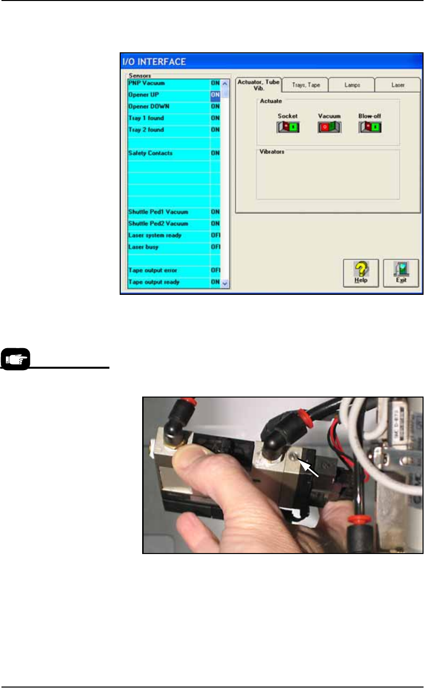
1b. Click Vacuum to the OFF position.
1c. Click Blow-off to the ON position.
Figure 4-9: Vacuum (shown OFF) and Blow-off (shown ON) on the
I/O Interface Window.
2. Vacuum generator—
2a. On top of the vacuum generator, locate the blow-off adjustment
screw above the valve coils (where the wires plug in). See Figure
4-10. The vacuum generator block at the main PNP head will
need to be removed for access.
Figure 4-10: The Blow-off adjustment screw on PNP head vacuum
generator.
3. Adjust—
3a. Turn the adjustment screw in fully clockwise. This blocks all air
and there is no blow-off (puff of air) at the PNP probe.
3b. Turn the adjustment screw 1/2 turn counterclockwise.
For instructions to remove the
Vacuum Generator at the
main PNP head see Vacuum
Generator Filters and Silenc-
ers on page 4-15.
■ Workspace, Head and Gantry ◘ Checking the Automatic Tray Feeder
PS Series Owner’s Manual 4—15
back
Checking the Automatic Tray Feeder
[TF20 Tray Feeder only]
1. Stop or Pause a job if one is running.
2. Check the automatic Tray Feeder for damaged or broken parts
and replace as necessary.
3. Visually inspect the conveyor belts for dirt, nicks, or other signs
of damage.
4. If the conveyor belts are dirty, clean with dry, compressed air
and wipe with a dry, lint-free cloth and isopropyl alcohol.
5. Check the urethane pinch roller attached to the tray clamping
mechanism for signs of wear or damage. Replace as necessary.
Clean with a dry, lint-free cloth and isopropyl alcohol.
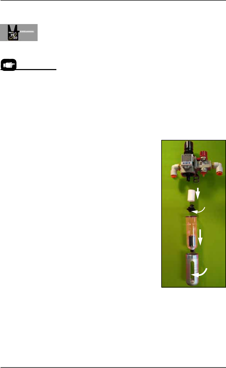
Replacing the Input Air Filter
1. Shut off shop air and disconnect the input air line from the Air
Filter/Regulator.
2. Unscrew the air contamination col-
lection bowl housing.
3. Pull off the clear collection bowl.
Clean out any dirt, oil, or water.
4. Unscrew the black knob below the
filter.
5. Pull off the filter. Clean or replace
as necessary.
Reinstall in reverse order being careful
not to damage the O-ring on the bowl.
Reconnect the shop air supply line.
Figure 4-11: Replacing the Air Filter/Regulator.
Vacuum Generator Filters and Silencers
This procedure covers removing and cleaning or replacing vacuum
generator parts for all vacuum generators on the PS Machine.
For more information see
the Tray Feeder manual that
came with your system.
Filter
Knob
Bowl
Bowl
hous-
ing
Maintenance ■ Workspace, Head and Gantry
4—16 Data I/O • 981-0424-002
back
PNP head: A clogged or dirty vacuum filter or silencer at this
vacuum generator can cause dropped devices and placement
problems at the PNP head.
Marking System: [Marking option] Two vacuum generators in
the Option Bay must be clean to ensure devices stay on the
marking shuttle.
Tape Output: [Output option] A clogged or dirty vacuum filter
or silencer at this vacuum generator can cause dropped devices
at the PNP Taping Head on the Tape Output Module.
1. Preparation—
1a. Use the Gantry Window to move the PNP head to an accessible
location.
1b. Shut off the PS System power and ensure the main power switch
is in the OFF position. See Turning Off the System on page 4-4.
WARNING: Electric shock hazard. Shut off the PS System
by
switching off the main power switch before working on or near
the PNP head, before opening any access doors or removing any
cabinet panels.
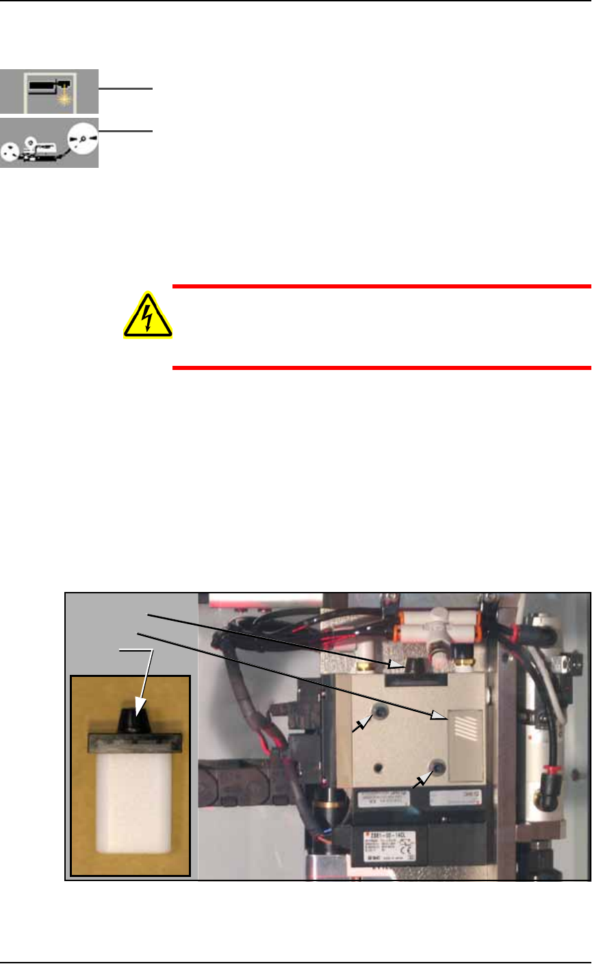
1c. Remove the two Vacuum Generator mounting screws with a
7/64 in. hex key and be ready to support it as it falls free. See Fig-
ure 4-12 below.
2. Check silencer and filter—
2a. Push the silencer out of the vacuum generator block (either
direction). If dirty or clogged, replace with new silencer
(Data I/O part number 288 5500 902). See the figure below.
2b. Unscrew the black knob on top the vacuum block and remove
the filter. It should be white or nearly white. If dirty or clogged,
replace with new filter (Data I/O part number 288 5500 901). See
the figure below.
Figure 4-12: Removing the PNP head Vacuum Generator filter and
silencer. The two small arrows point to the Mounting screws.
Filter knob
Silencer
Filter