PS288_PS388_PS588_981-0424-002D - 第157页
■ Workspace, Head and Gantry ◘ Vacuum Generator Filters and Silencers PS Series Owner’s Manual 4—17 back 3. Reinstall V acuum Generator— 3a. Reinstall the generator (after installing a filt er and silencer). 4. [ Marking…
Maintenance ■ Workspace, Head and Gantry
4—16 Data I/O • 981-0424-002
back
PNP head: A clogged or dirty vacuum filter or silencer at this
vacuum generator can cause dropped devices and placement
problems at the PNP head.
Marking System: [Marking option] Two vacuum generators in
the Option Bay must be clean to ensure devices stay on the
marking shuttle.
Tape Output: [Output option] A clogged or dirty vacuum filter
or silencer at this vacuum generator can cause dropped devices
at the PNP Taping Head on the Tape Output Module.
1. Preparation—
1a. Use the Gantry Window to move the PNP head to an accessible
location.
1b. Shut off the PS System power and ensure the main power switch
is in the OFF position. See Turning Off the System on page 4-4.
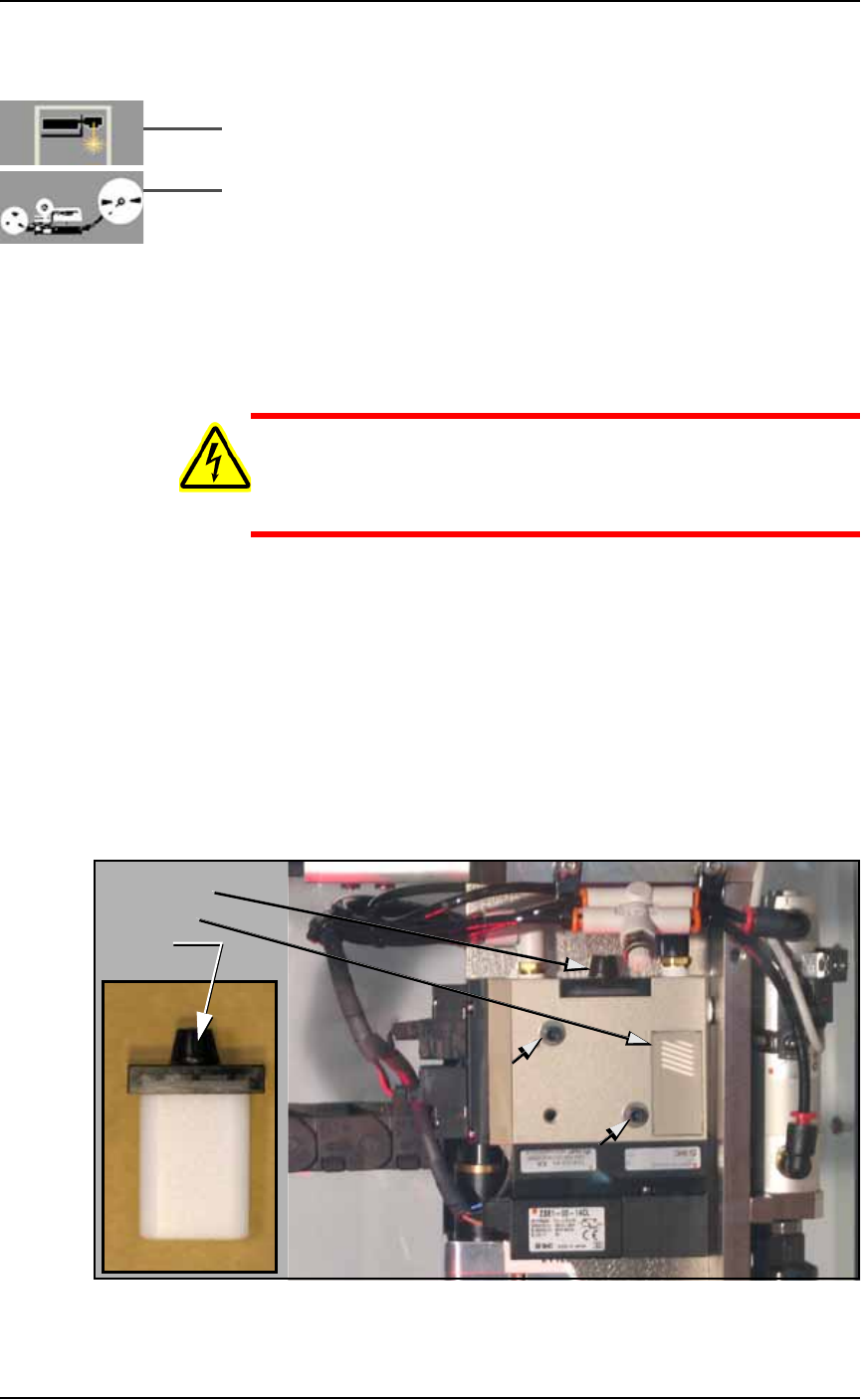
WARNING: Electric shock hazard. Shut off the PS System
by
switching off the main power switch before working on or near
the PNP head, before opening any access doors or removing any
cabinet panels.
1c. Remove the two Vacuum Generator mounting screws with a
7/64 in. hex key and be ready to support it as it falls free. See Fig-
ure 4-12 below.
2. Check silencer and filter—
2a. Push the silencer out of the vacuum generator block (either
direction). If dirty or clogged, replace with new silencer
(Data I/O part number 288 5500 902). See the figure below.
2b. Unscrew the black knob on top the vacuum block and remove
the filter. It should be white or nearly white. If dirty or clogged,
replace with new filter (Data I/O part number 288 5500 901). See
the figure below.
Figure 4-12: Removing the PNP head Vacuum Generator filter and
silencer. The two small arrows point to the Mounting screws.
Filter knob
Silencer
Filter
■ Workspace, Head and Gantry ◘ Vacuum Generator Filters and Silencers
PS Series Owner’s Manual 4—17
back
3. Reinstall Vacuum Generator—
3a. Reinstall the generator (after installing a filter and silencer).
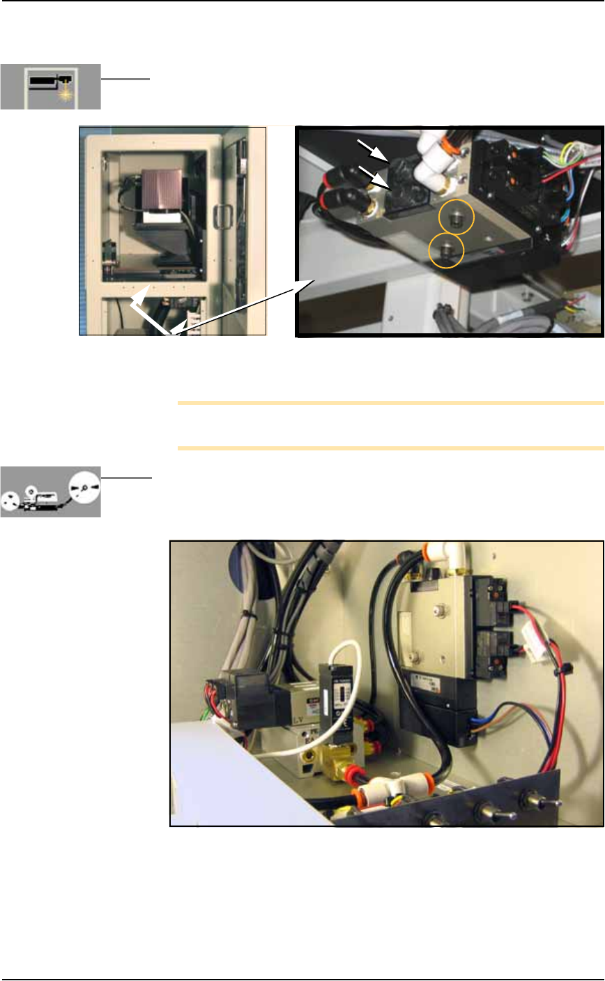
4. [Marking System only] Repeats steps 1b through 3a above for
two more Vacuum Generators mounted inside the Option Bay
under the laser support plate. See figure below.
Figure 4-13: Two Vacuum Generators on the Laser Marker. Arrows
point to the filters. Two screws secure both Vacuum block (circled).
Note: The Tape-Output has a Data I/O-installed PNP Taping
Head.
5. [Tape Out Module only] Remove the front panel of the box
supporting the Tape Out Module (1/8 inch Hex Key) and then
repeat steps 1b through 3a above for the additional Vacuum
Generator mounted inside the control box. See figure below.
Figure 4-14: A Vacuum Generator on the TM50 Taping Module. The
front panel has been removed with a 1/8 in. hex key (six SHCS).
Maintenance ■ Workspace, Head and Gantry
4—18 Data I/O • 981-0424-002
back
Adjusting the Vacuum Generator
Sensors
Note: If you notice consecutive programming pick errors, before
adjusting vacuum sensors complete the Z-Axis adjustment. For
instructions on Z-Axis adjustment, see Teaching the Package File
on page 3-40. If completing the Z-Axis adjustment does not reduce
or eliminate subsequent pick errors, complete the vacuum sensor
adjustments described here.
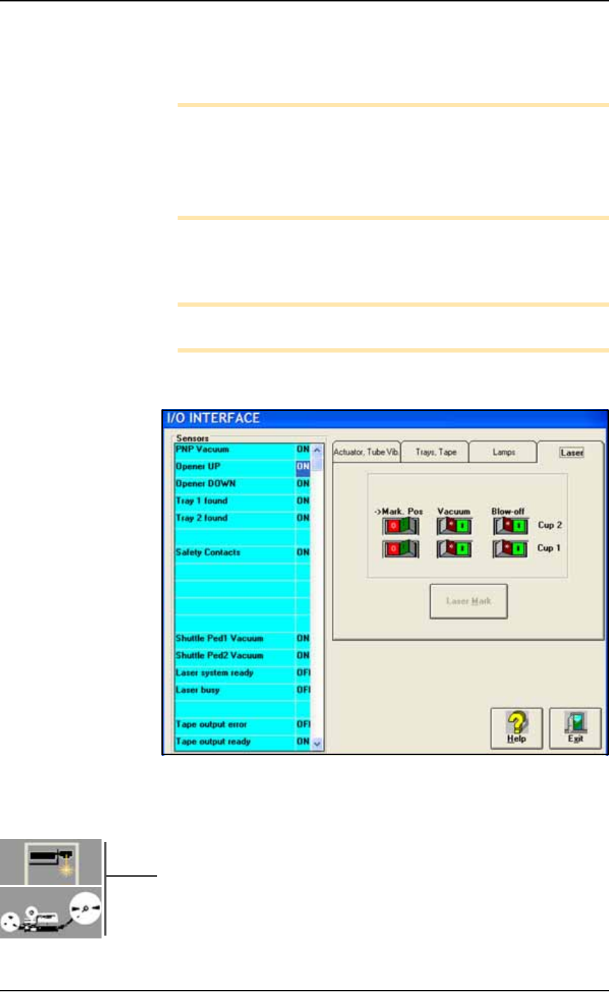
Vacuum sensors on the PS System are adjustable. The I/O Interface
window displays a list of the sensors in the PS System and the status
of each sensor.
Note: The number of sensors on the PS System depends on the
options installed.
To view the status of sensors at the main AH500 Setup window, click
System > Misc. I/O.
Figure 4-15: The I/O Interface window reports sensor status and allows
switching options on or off. PS588 shown.
Sensor Locations
• PNP Head Vacuum Generator Sensor:
An adjustable vacuum generator sensor on the PNP head con-
trols probe vacuum. See heading below.
•[Laser Marking or Tape Output only] Shuttle Pedestal 1 and 2
Vacuum Generator Sensors on page 4-21:
Either of these options on your PS Machines include adjustable