PS288_PS388_PS588_981-0424-002D - 第159页
■ Workspace, Head and Gantry ◘ Adjusting the Vacuum Gene rator Sensors PS Series Owner’s Manual 4—19 back va cuum generator sensors for the Shuttle T ransfer System con- trolling v acuum at the shuttles. •[ T ape Output …
Maintenance ■ Workspace, Head and Gantry
4—18 Data I/O • 981-0424-002
back
Adjusting the Vacuum Generator
Sensors
Note: If you notice consecutive programming pick errors, before
adjusting vacuum sensors complete the Z-Axis adjustment. For
instructions on Z-Axis adjustment, see Teaching the Package File
on page 3-40. If completing the Z-Axis adjustment does not reduce
or eliminate subsequent pick errors, complete the vacuum sensor
adjustments described here.
Vacuum sensors on the PS System are adjustable. The I/O Interface
window displays a list of the sensors in the PS System and the status
of each sensor.
Note: The number of sensors on the PS System depends on the
options installed.
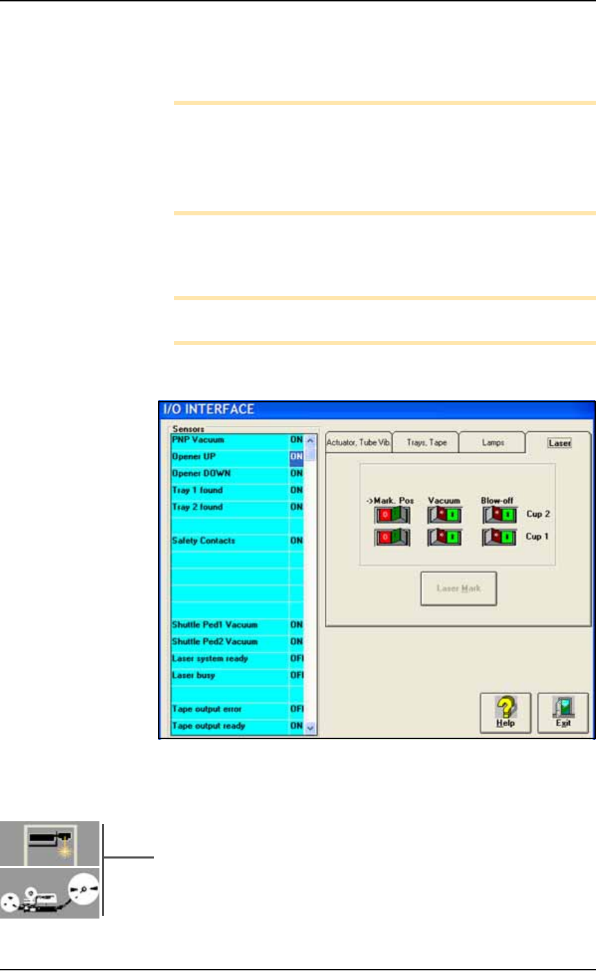
To view the status of sensors at the main AH500 Setup window, click
System > Misc. I/O.
Figure 4-15: The I/O Interface window reports sensor status and allows
switching options on or off. PS588 shown.
Sensor Locations
• PNP Head Vacuum Generator Sensor:
An adjustable vacuum generator sensor on the PNP head con-
trols probe vacuum. See heading below.
•[Laser Marking or Tape Output only] Shuttle Pedestal 1 and 2
Vacuum Generator Sensors on page 4-21:
Either of these options on your PS Machines include adjustable
■ Workspace, Head and Gantry ◘ Adjusting the Vacuum Generator Sensors
PS Series Owner’s Manual 4—19
back
vacuum generator sensors for the Shuttle Transfer System con-
trolling vacuum at the shuttles.
•[Tape Output only] Tape Output PNP Head Vacuum Generator
Sensor on page 4-23. The adjustable vacuum generator sensor on
the Tape Output PNP head controls vacuum at the probe.
PNP Head Vacuum Generator Sensor
To adjust the PNP head vacuum generator sensor:
1. Gantry Window—
1a. On the Gantry Window, move the PNP head to either the Tape
or Vision location.
Note: To move the PNP head, tap the Tape or Vision label on the
monitor or use the touch pad and left touch pad button .
1b. Click the Gantry Vacuum switch to ON.
1c. Push the E-stop.
CAUTION: Collision hazard! The high speed and force behind a
moving gantry can cause serious bodily injury to anyone working
inside the work envelope. Ensure that a job is Paused, the Emer-
gency-Stop is pushed, or the power is off prior to opening work-
space doors.
2. Vacuum sensor—
2a. Open the workspace door.
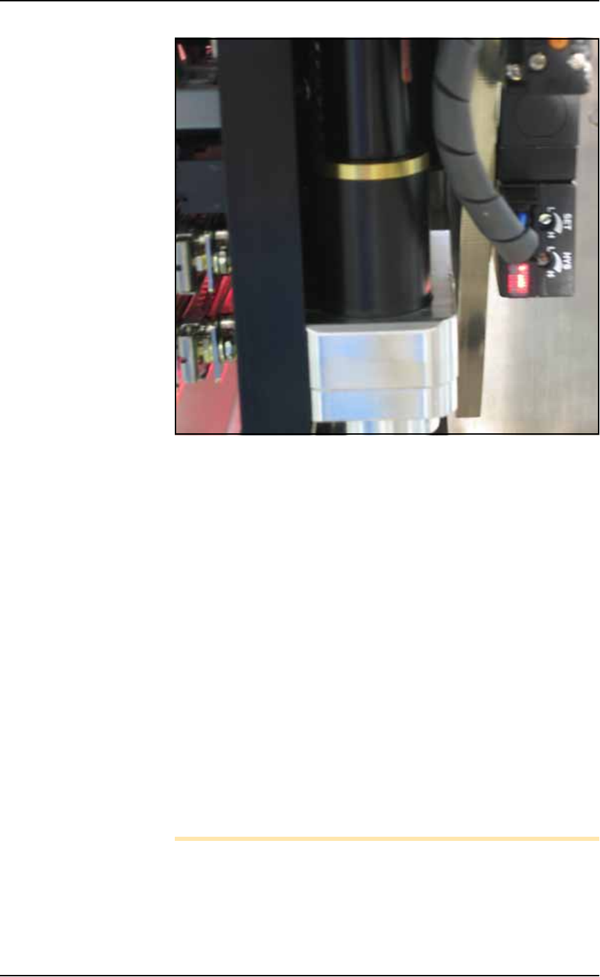
2b. On the vacuum generator sensor, locate the adjustment screws
labeled HYS and SET. Locate the red sensor light. See Figure
4-16.
Maintenance ■ Workspace, Head and Gantry
4—20 Data I/O • 981-0424-002
back
Figure 4-16: The PNP Probe vacuum generator adjustments. Your
PNP head may not look like this.)
3. Adjust the HYS and SET screws—
3a. Locate the HYS and SET screws on the vacuum generator block.
Using a small flat screwdriver, turn the hysteresis adjustment
(HYS) screw all the way counterclockwise.
3b. Then rotate the SET adjustment screw counterclockwise until
the red sensor light comes on.
3c. Then rotate the SET screw clockwise just until the red light goes
off.
3d. Finally rotate the SET screw another 1/8th revolution clockwise.
4. Check adjustments—
4a. Block the hole on the PNP probe with a device. The red sensor
light should come on immediately.
4b. Unblock the hole. The red sensor light should go off immedi-
ately.
5. Repeat—
5a. Repeat Step 4 three times to ensure the red sensor light goes on
and off as described.
5b. If the red sensor light does not go off and on properly, rotate the
SET screw slightly clockwise and retry.
Note: IF the PS System displays a vacuum error, it may be due to
the vacuum generator’s inability to sense a vacuum within the time
limits set in the AH500 software.
The hysteresis delay should be set as short as possible to prevent the