PS288_PS388_PS588_981-0424-002D - 第161页
■ Workspace, Head and Gantry ◘ Adjusting the Vacuum Gene rator Sensors PS Series Owner’s Manual 4—21 back SW from timing out. However , if the hysteresis delay is set too short, vacuum line pulsations fr om usage through…
Maintenance ■ Workspace, Head and Gantry
4—20 Data I/O • 981-0424-002
back
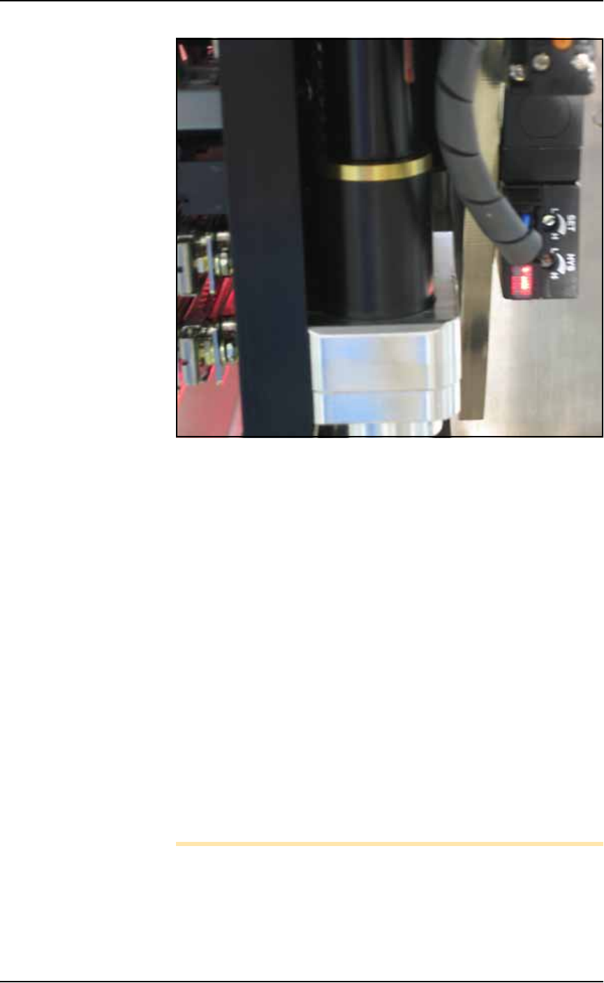
Figure 4-16: The PNP Probe vacuum generator adjustments. Your
PNP head may not look like this.)
3. Adjust the HYS and SET screws—
3a. Locate the HYS and SET screws on the vacuum generator block.
Using a small flat screwdriver, turn the hysteresis adjustment
(HYS) screw all the way counterclockwise.
3b. Then rotate the SET adjustment screw counterclockwise until
the red sensor light comes on.
3c. Then rotate the SET screw clockwise just until the red light goes
off.
3d. Finally rotate the SET screw another 1/8th revolution clockwise.
4. Check adjustments—
4a. Block the hole on the PNP probe with a device. The red sensor
light should come on immediately.
4b. Unblock the hole. The red sensor light should go off immedi-
ately.
5. Repeat—
5a. Repeat Step 4 three times to ensure the red sensor light goes on
and off as described.
5b. If the red sensor light does not go off and on properly, rotate the
SET screw slightly clockwise and retry.
Note: IF the PS System displays a vacuum error, it may be due to
the vacuum generator’s inability to sense a vacuum within the time
limits set in the AH500 software.
The hysteresis delay should be set as short as possible to prevent the
■ Workspace, Head and Gantry ◘ Adjusting the Vacuum Generator Sensors
PS Series Owner’s Manual 4—21
back
SW from timing out. However, if the hysteresis delay is set too
short, vacuum line pulsations from usage throughout the system
could inadvertently switch the sensor on when it should be off.
Adjustments should be made to accommodate both conditions.
Shuttle Pedestal 1 and 2 Vacuum Generator Sensors
[Laser Marking or Tape Output only]
1. Preparation—
1a. On the back of the PS System, turn the SERVOS circuit breaker
OFF.
1b. Remove the lower right access cover of the Option Bay and set
aside. See Figure 4-13 on page 4–17.
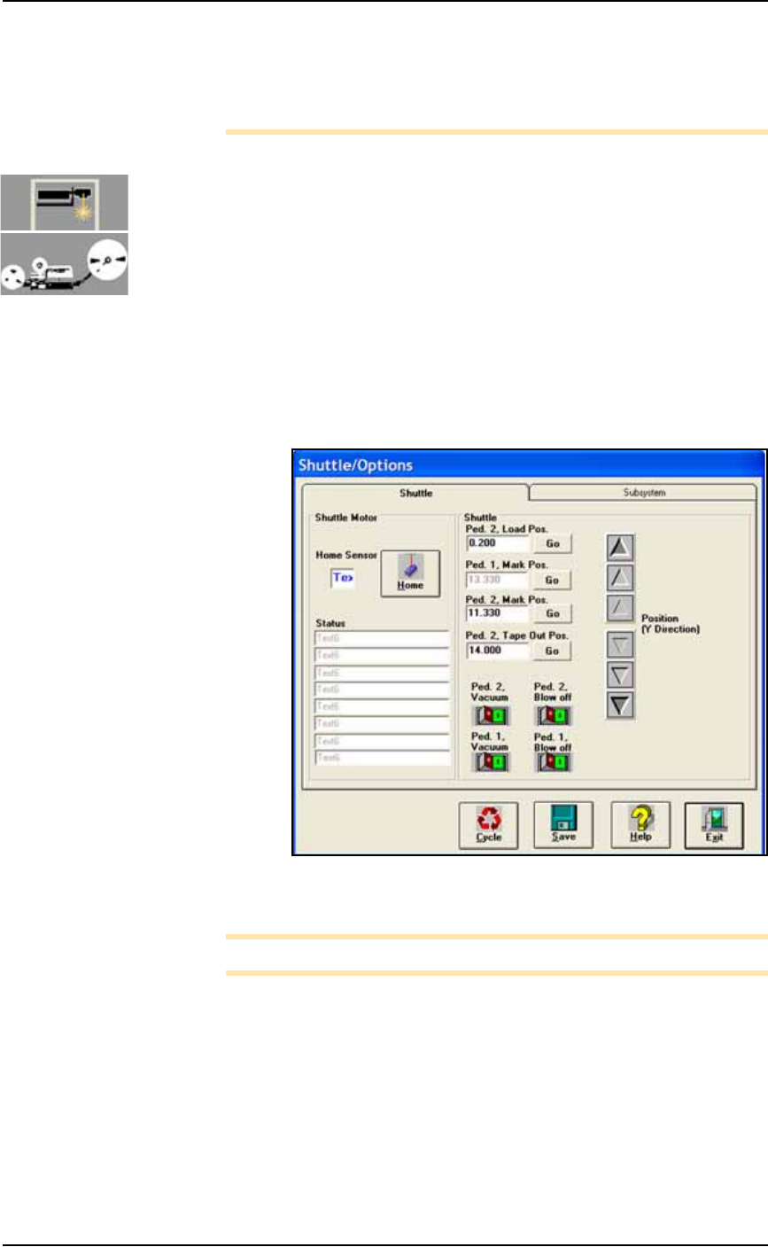
1c. At the SYSTEM window, click Shuttle/Options.
2. Switch Ped 2 Vacuum ON—
2a. At the Shuttle tab, click GO next to Ped 2 Load Pos. Then click the
Ped 2 Vacuum to ON. See Figure 4-17.
.
Figure 4-17: The Shuttle Tab of the Shuttle/Options Window. PS588
shown.
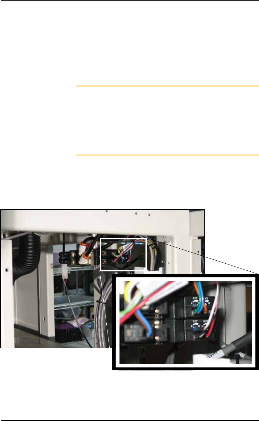
Note: Refer to Figure 4-18 for Step 3 through Step 5.
3. Adjust Pedestal [2] HYS and SET screws—
3a. Locate the HYS and SET screws on the vacuum generator block.
Using a small flat screwdriver, rotate the hysteresis (HYS) screw
all the way counterclockwise. See Figure 4-18.
3b. Then rotate the SET screw counterclockwise until the red vac-
uum sensor lamp comes on.
3c. Then rotate the SET screw clockwise until the lamp goes off.
3d. Finally rotate the SET screw another 1/8th revolution clockwise.
Maintenance ■ Workspace, Head and Gantry
4—22 Data I/O • 981-0424-002
back
4. Check adjustment—
4a. Block the hole on the shuttle pedestal with a device. The red vac-
uum sensor lamp should come on immediately.
4b. Unblock the hole. The red vacuum sensor lamp should go off
immediately.
4c. Repeat check to ensure the red vacuum sensor lamp goes on and
off as described.
4d. If the red vacuum sensor lamp does not go off and on properly,
rotate the SET screw slightly clockwise and retry.
Note: If the PS System displays a vacuum error, it may be due to
the vacuum generator’s inability to sense a vacuum within the time
limits set in the AH500 software.
The hysteresis delay should be set as short as possible to prevent the
SW from timing out. However, if the hysteresis delay is set too
short, vacuum line pulsations from usage throughout the system
could inadvertently switch the sensor on when it should be off.
Adjustments should be made to accommodate both conditions.
5. Switch Ped 1 Vacuum ON—
5a. At the Shuttle tab, click Ped 2 Vacuum to OFF.
5b. Click Ped 1 Vacuum to ON.
6. Adjust Pedestal 1 HYS and SET screw—
6a. Repeat Step 3 and Step 4 for Pedestal 1.
Figure 4-18: Pedestal 1 and Pedestal 2 vacuum generator adjust-
ments. Pedestal 1 vacuum generator is on top.