PS288_PS388_PS588_981-0424-002D - 第164页
Maintenance ■ Workspace, Head and Gantry 4—24 Data I/O • 981-0424 -002 back 2b. Then rotate SET screw counterclockwise until the red vacuum sensor lamp comes on. 2c. Then rotate the SET screw clockwise until the lamp goe…
■ Workspace, Head and Gantry ◘ Adjusting the Vacuum Generator Sensors
PS Series Owner’s Manual 4—23
back
7. Shuttle tab—
7a. At the Shuttle tab, click Ped 1 Vacuum to OFF.
7b. Click Ped 2 Vacuum to OFF.
8. Reinstall the access cover on the Option Bay.
Tape Output PNP Head Vacuum Generator Sensor
[Tape Output only]
If your system includes the optional Tape Output System, you will
also need to adjust the vacuum generator sensor on the Tape Output
PNP head.
1. Preparation—
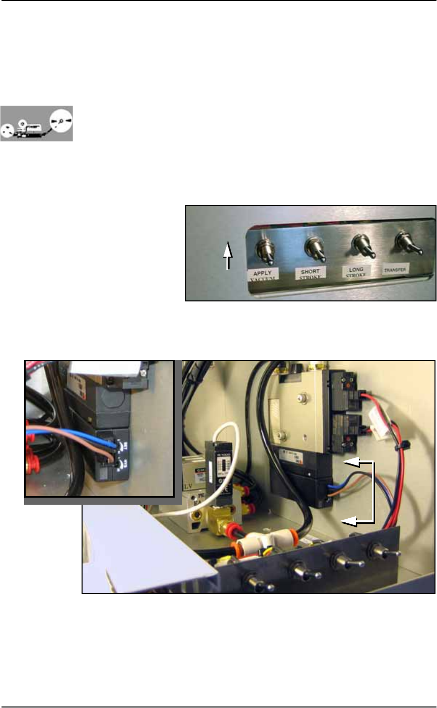
1a. On the PLC Controller, switch the Apply Vacuum toggle to the
ON (up) position. See Figure 4-19.
Figure 4-19: Apply Vacuum switch: UP is on.
1b. With a 1/8 inch Hex Key, remove the front panel by removing
the six SHCS (Socket Head Cap screws).
Figure 4-20: Tape Output vacuum generator adjustments.
2. Adjust the HYS and SET—
2a. Locate the HYS and SET screws on the vacuum generator block.
See Figure 4-20. Using a small, flat screwdriver, rotate the hyster-
esis (HYS) screw counterclockwise.
A
A
A-A

Maintenance ■ Workspace, Head and Gantry
4—24 Data I/O • 981-0424-002
back
2b. Then rotate SET screw counterclockwise until the red vacuum
sensor lamp comes on.
2c. Then rotate the SET screw clockwise until the lamp goes off.
2d. Finally rotate the SET screw another 1/8th revolution clockwise.
3. Check adjustments—
3a. Open the plastic cover on the Tape Output System and block the
air hole at the Tape-Output-PNP head probe wit a device. The
red vacuum sensor lamp should light immediately.
3b. Unblock the hole. The red vacuum sensor lamp should extin-
guish immediately.
4. Repeat—
4a. Test several times to ensure the red vacuum sensor lamp lights
and dims as described. If the red vacuum sensor lamp does not
go off and on properly, turn the SET screw clockwise a few
degrees and retry.
5. Complete—
5a. Close the clear plastic cover.
5b. Replace the front panel.
Note: If the PS System displays a vacuum error, it may be due to
the vacuum generator’s inability to sense a vacuum within the time
limits set in the AH500 software.
The hysteresis delay should be set as short as possible to prevent the
software from timing out. However, if the hysteresis delay is set too
short, vacuum line pulsations from usage throughout the system
could inadvertently switch the sensor on when it should be off.
Adjustments should be made to accommodate both conditions.
Inspecting Gantry Parts
Checking the PNP Head and Gantry Wiring Harnesses
1. Check—
1a. Switch the PS System main power switch OFF. Verify that the
main power switch is in the OFF position.
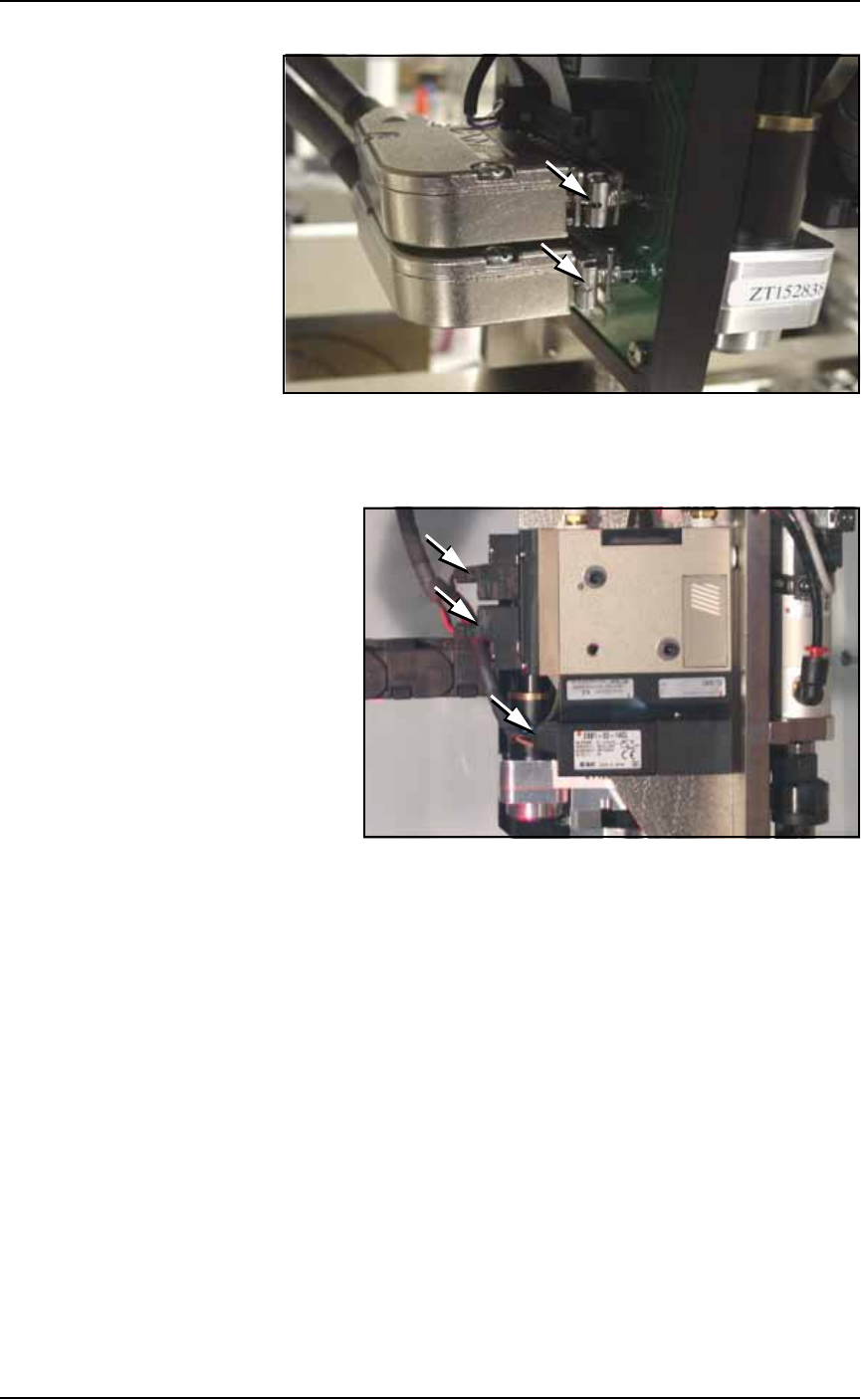
1b. Check the retaining clips on the two DB25 connectors plugged
into the PNP head. They slide back (away from the operator) to
release. Make sure they are slid forward. See Figure 4-21.
■ Workspace, Head and Gantry ◘ Inspecting Gantry Parts
PS Series Owner’s Manual 4—25
back
Figure 4-21: PNP head sliding retaining clips.
1c. Check gantry wiring harness plug connections and make sure
that they are secure. See Figure 4-22.
Figure 4-22: Three electrical connections on the Vacuum Generator.
Inspecting Gantry Cable Carriers
1. Clean—
1a. Use dry compressed air to remove all foreign material from the
cable carriers.
2. Check—
2a. Visually check that the cables are in good condition, and are not
too loose or too tight.
2b. Check by hand that the upper end of the upper carrier is tight. If
not, tighten the two mounting screws. Cable ties may need to be
cut to move the cables out of the way. See Figure 4-23.