PS288_PS388_PS588_981-0424-002D - 第167页
■ Workspace, Head and Gantry ◘ Inspecting Gantry Parts PS Series Owner’s Manual 4—27 back Figure 4-25: The two cable carriers meet at a brack et at t he back of the PS System. There are two screws for each carrier end. V…
Maintenance ■ Workspace, Head and Gantry
4—26 Data I/O • 981-0424-002
back
Figure 4-23: Looking up from the back of the system, the upper end of
the upper cable carrier is screwed to the frame.
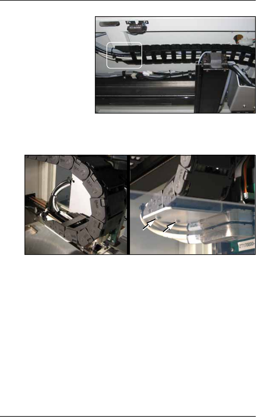
2c. Check the two screws on the lower end of the lower cable carrier
and tighten if necessary. See Figure 4-24.
Figure 4-24: The lower end of the lower cable carrier: A- from above,
and B-from below.
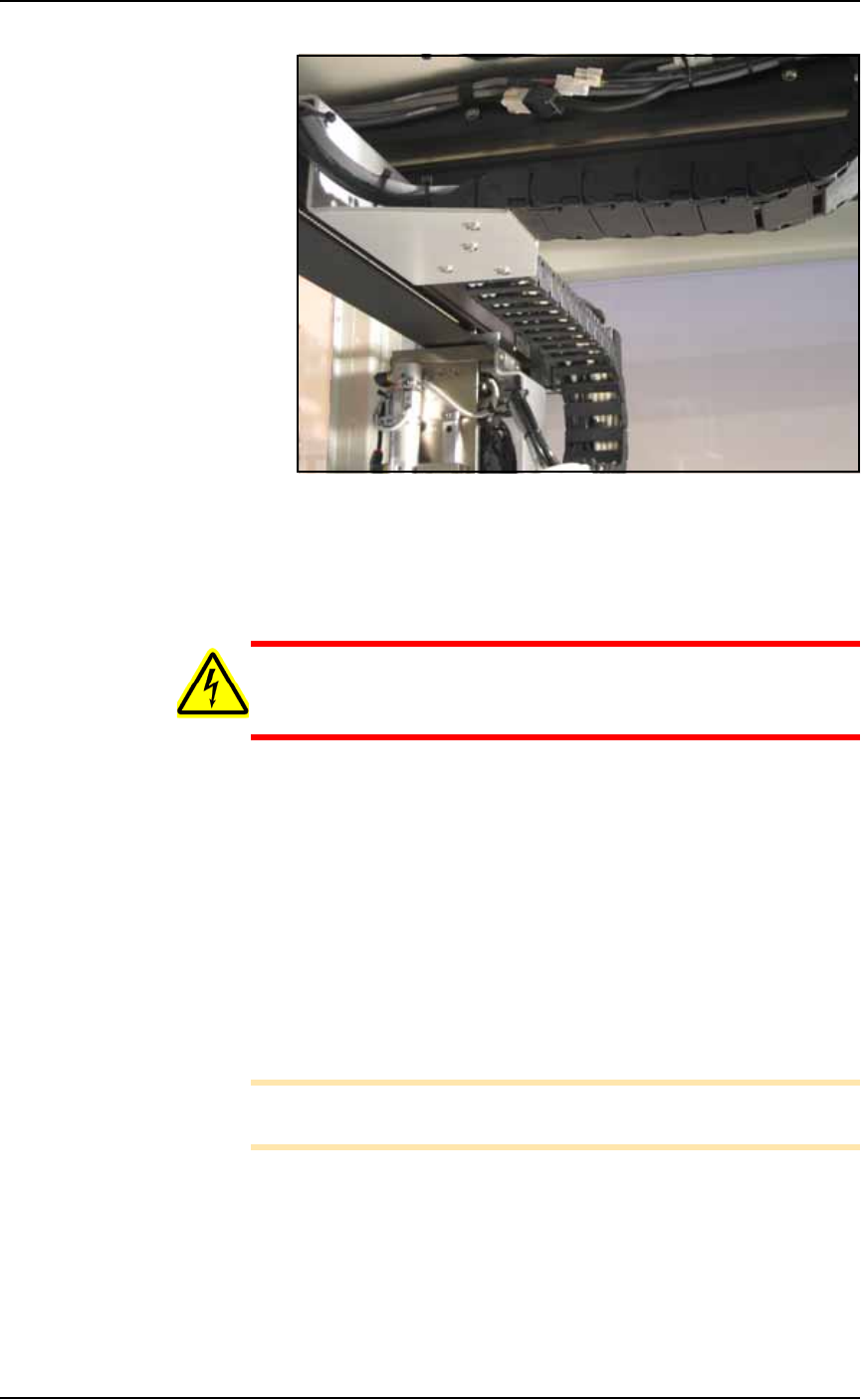
2d. Check the four screws on the center carrier and tighten if neces-
sary. See Figure 4-25.
A
B
■ Workspace, Head and Gantry ◘ Inspecting Gantry Parts
PS Series Owner’s Manual 4—27
back
Figure 4-25: The two cable carriers meet at a bracket at the back of
the PS System. There are two screws for each carrier end. View looking
upward from the back of the machine.
Lubricating the Gantry Lead Screw
WARNING: Electric shock hazard. Shut off the PS System power
(Turning Off the System on page 4-4) — switch off the main
power switch before removing the lead screw shields.
1. Preparation—
1a. Shut off the PS System power and ensure the main power switch
is in the OFF position.
1b. Remove the screws that hold the Lead Screw Shield to the gantry
rails.
1c. Remove the shield.
2. Remove the old grease and dirt build up from the lead screw
using shop towels.
3. Apply new grease—
3a. Apply NSK Grease (or equivalent) to the lead screw grease fit-
ting using an MG70 (or equivalent) grease gun. See Figure 4-26.
Note: Too much grease may cause grease to splatter inside the work
envelope. Do not over-apply the grease.

Maintenance ■ Workspace, Head and Gantry
4—28 Data I/O • 981-0424-002
back
Figure 4-26: Grease fitting
4. Reinstall the Lead Screw Shield.