PS288_PS388_PS588_981-0424-002D - 第173页
■ Programmers ◘ Removing a Programmer PS Series Owner’s Manual 4—33 back [PS588 only] Removing an Optima (Universal) Programmer T o replace an individual Optima programmer assembly: 1. Preparation— 1a. Switch the PS588 p…
Maintenance ■ Programmers
4—32 Data I/O • 981-0424-002
back
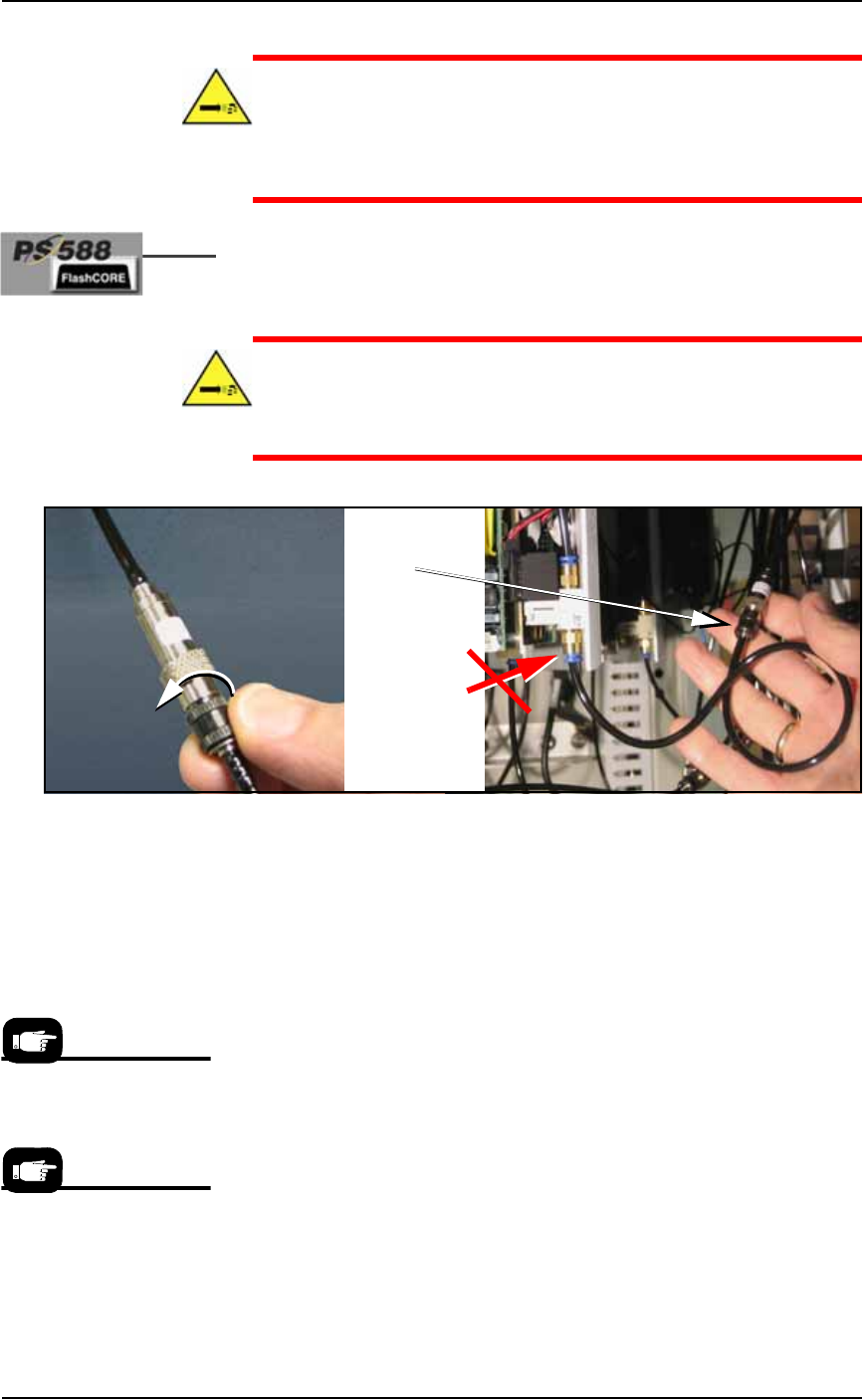
CAUTION: Pressurized air hazard. The main air line is connected
and ON. If the wrong air fitting is disconnected, the tube will fly
about until the main air valve at the back of the machine is
switched off. For the correct programmer connector, see Figure
4-28.
2c. [PS588 only] Disconnect the air hose by unscrewing the pro-
grammer-side of the automatic shut-off union shown in the fig-
ure below.
WARNING: Pressurized air hazard. If your model does not have
the inline, automatic shut-off union shown in Figure 4-28, then
switch off (or disconnect) the main air supply at the Power Panel
before disconnecting any air lines.
Figure 4-28: [PS588 only] Unscrew the black collar on the air fitting as
shown.
3. Remove programmer assembly—
3a. Remove the three mounting screws (single) or five mounting
screws (dual) that hold the FlashCORE programmer assembly to
the top plate with a 1/8 inch hex key.
3b. Carefully lift out the FlashCORE programmer assembly.
4. Installing—
4a. Install a new FlashCORE programmer assembly in reverse order
of removal.
5. Update firmware—
The newly installed FlashCORE programmer assembly must be
located and assigned a site number with TaskLink. Once the site
is assigned, firmware on the new FlashCORE programmer
assembly must be updated from TaskLink.
6. Update programmer date/time—
This TaskLink feature sets the date and time on each connected
FlashCORE programmer so that the Log files report accurate
time and date information. See TaskLink’s on-screen Help for
information on how to view log files.
Disconnect air
here . . .
. . . NOT here.
see Caution
note
For information about
updating firmware see
TaskLink’s on-screen Help.
For information on setting
programmer date and
time, see TaskLink’s
on-screen Help.
■ Programmers ◘ Removing a Programmer
PS Series Owner’s Manual 4—33
back
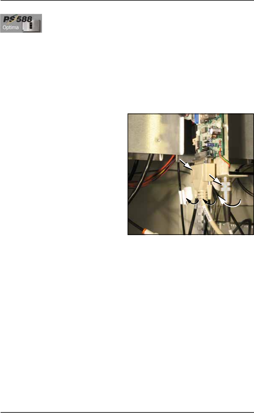
[PS588 only] Removing an Optima (Universal)
Programmer
To replace an individual Optima programmer assembly:
1. Preparation—
1a. Switch the PS588 power off at the main power switch.
1b. Lift the Socket Adapter off the programmer if there is one.
1c. Open the outer access panel closest to the target programmer.
2. Disconnect—
2a. Remove the parallel cable by unscrewing the two small, captive
screws.
2b. Remove the second cable by unscrewing the connector and pull-
ing off.
Figure 4-29: Optima (Universal) Programmer Cables.
3. Unscrew and remove—
3a. Unscrew the screws mounting the programmer to the work sur-
face (there are four or six, depending on programmer) with a
1/8 inch hex key.
3b. Carefully lift out the assembly.
4. Installing—
4a. Installation is in reverse order of removal. Orient the program-
mer with the PCB on the outboard side of the PS588 center line.
Maintenance ■ The Marking Systems and Shuttle
4—34 Data I/O • 981-0424-002
back
The Marking Systems and Shuttle
[Label or Laser Marking only] Laser Marker and Label Marker Sys-
tems are optional equipment on your PS Programming System. Your
PS Machine may not have either. Each marking system requires some
maintenance. Both have a computer with filter, and both have a
marker Shuttle Assembly. The Tape Out System also uses a Shuttle
Assembly. In addition, Laser Markers have fume extractors.
The Shuttle Assembly
Whether you have a Laser Marker or Label Marker System, Shuttle
Transfer Assemblies attached to a belt transport devices to and from
the marker. The Shuttle Assembly requires periodic maintenance.
Cleaning the Shuttle Assembly
During extended or heavy periods of use, the shuttle assembly may
become dirty and gummed up by laser dust or other foreign material.
This situation may cause the shuttle assembly to stall during move-
ment to and from the laser mark position.
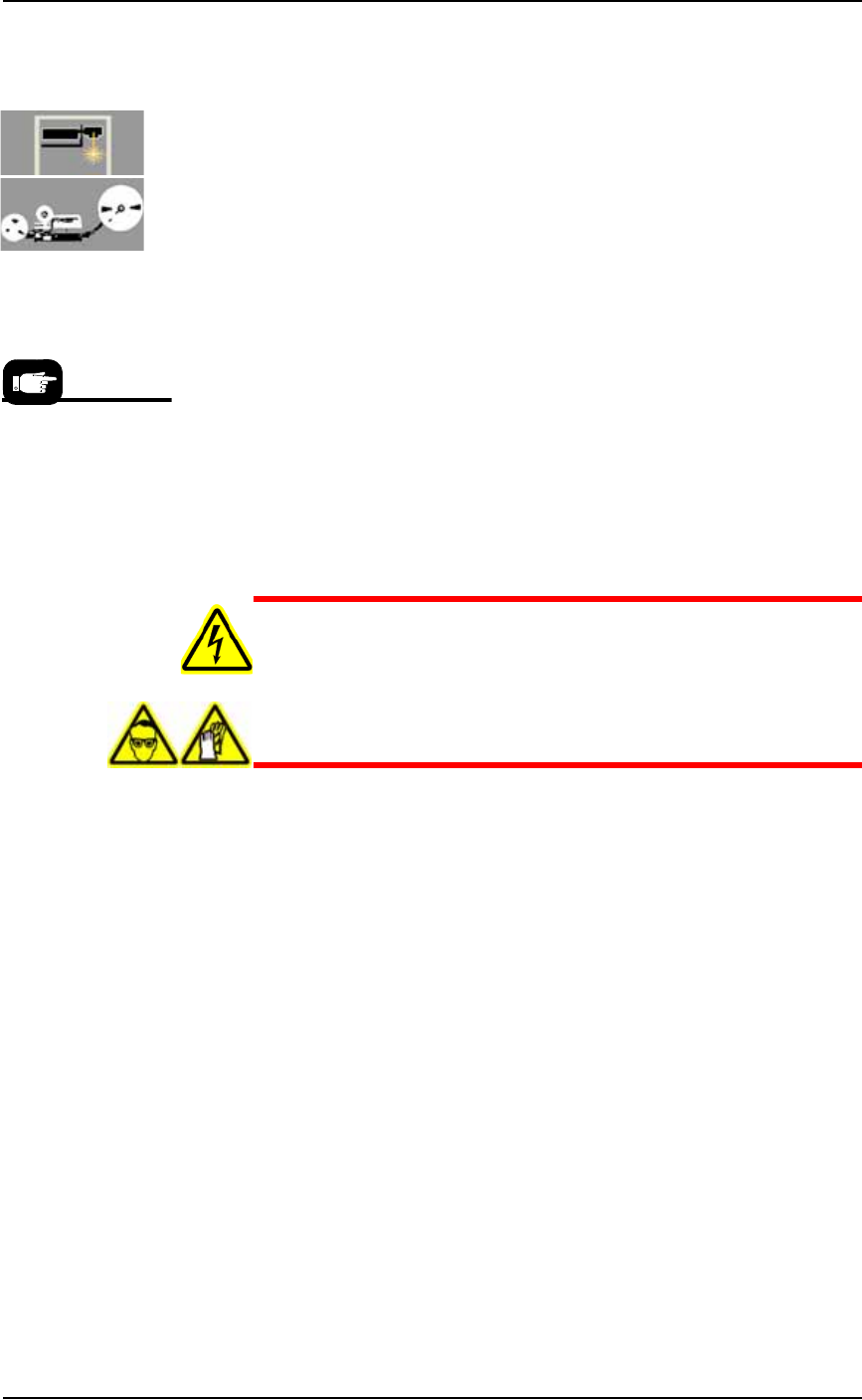
WARNING: Electric shock hazard. Shut off the PS System (Turn-
ing Off the System on page 4-4) and switch off the main power
switch.
Hazardous materials: Do not use compressed air to remove laser
dust. Wear safety goggles and disposable protective gloves.
To clean the laser marker shuttle assembly:
1. Preparation—
1a. Shut off the PS System power and ensure the main power switch
is in the OFF position.
1b. Put on safety goggles and disposable protective gloves.
1c. Remove the upper left Option Bay panel (1/8 in. Hex Key) to
access the laser housing. See Figure 4-30. Remove Option Bay
panels as needed for cleaning the laser marking system.
The Shuttle Assembly
information here also
applies to systems
with the optional Tape
Output. Other Tape
Output information
can be found later in
this chapter.