PS288_PS388_PS588_981-0424-002D - 第176页
Maintenance ■ The Marking Systems and Shuttle 4—36 Data I/O • 981-0424 -002 back Adjusting Shuttle Belt T ension [ Label or Laser Marking only ] CAUTION: Health hazard. The La ser Marking System should be cleaned as desc…
■ The Marking Systems and Shuttle ◘ The Shuttle Assembly
PS Series Owner’s Manual 4—35
back
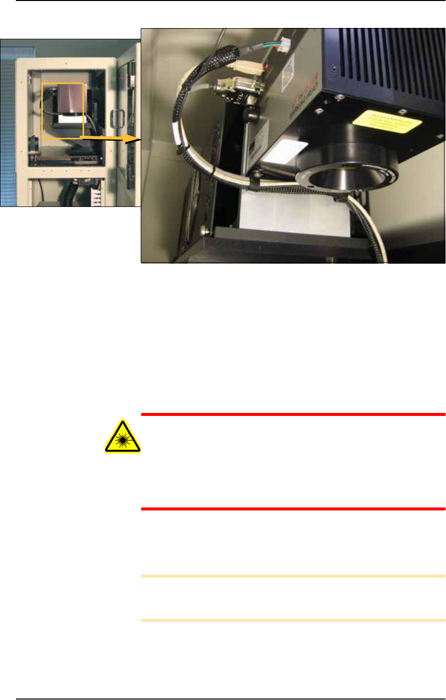
Figure 4-30: Left end of the laser housing with lens. The Option Bay left
side panels have been removed.
2. Clean—
2a. Use a damp paper towel and antistatic cleaner to wipe laser
marking dust and other foreign material from the housing into a
sealable plastic bag.
2b. Clean the shuttle track using a lint-free cloth.
2c. Place paper towels, cloth, and protective gloves into a sealable
plastic bag. Seal the bag and dispose of as hazardous waste.
Remove safety goggles.
WARNING: Numerous government regulations apply to the stor-
age of hazardous waste. Ensure that contaminated filters are
properly labeled and stored in your hazardous waste storage
area. Also, make sure that they are not stored on your site longer
than government regulations allow (the typical limit is 90 days).
Check your government (local, state, and federal) regulations for
hazardous waste storage requirements.
3. Lubricate—
3a. Lubricate the bearing block and shuttle track with Tri-Flow
lubricant.
Note: Use a small amount of lubricant, just enough to allow the
bearing block to move freely on the track. Too much lubricant will
aid in the build up of contamination and cause stalling.
4. Reinstall—
4a. Reinstall all Option Bay panels.
Maintenance ■ The Marking Systems and Shuttle
4—36 Data I/O • 981-0424-002
back
Adjusting Shuttle Belt Tension
[Label or Laser Marking only]
CAUTION: Health hazard. The Laser Marking System should be
cleaned as described in The Shuttle Assembly on page 4-34 prior
to performing work.
WARNING: Electric shock hazard. Shut off the PS System main
power switch before removing any panels.
1. Preparation—
1a. Shut off the PS System power and ensure the main power switch
is in the OFF position. For more information see Turning Off the
System on page 4-4.
1b. Remove the upper left Option Bay panel.
2. Check the belt for wear and replace if necessary.
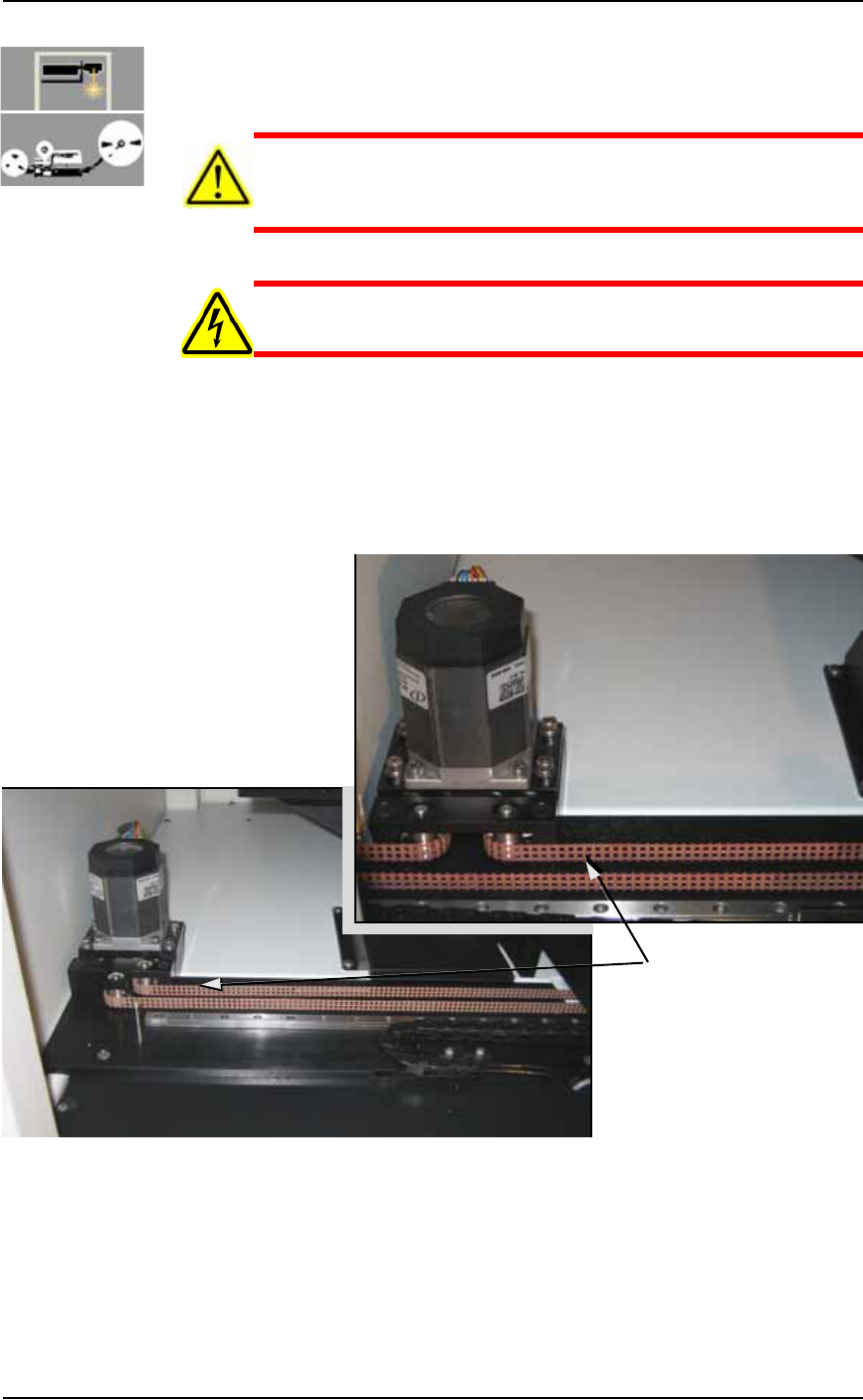
Figure 4-31: Marker Shuttle belt and motor, with Tape Out (A) and
without (B).
3. Test the tension by pulling lightly on the center of the shuttle
belt to the right of the motor. See Figure 4-31. If the belt moves
more than 12 mm (0.5 inch) off its path, loosen the four motor
mounting plate screws with a 4 mm hex key (see Figure 4-32),
Test tension here
A
B
■ The Marking Systems and Shuttle ◘ The Shuttle Assembly
PS Series Owner’s Manual 4—37
back
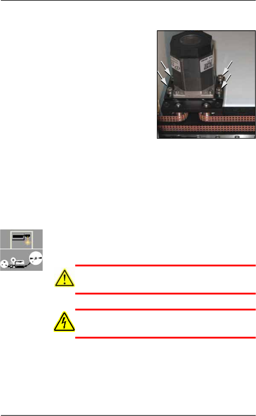
and then push the motor away from the belt until the belt move-
ment is less than 12 mm.
Figure 4-32: Location of four motor mounting plate screws.
3a. If the belt still moves more than 12 mm (0.5 inch), remove it and
cut off as many links as needed to achieve the proper tension.
3b. Replace the belt and tighten the four motor mounting screws.
4. Check the belt sprocket set screws—
4a. Check the belt sprocket set screws and tighten if necessary.
4b. If a sprocket has loosened and is rubbing against the frame,
reposition the sprocket up off the frame and tighten the set
screw.
4c. Reinstall all panels.
Replacing a Shuttle Belt
[Label or Laser Marking, or Tape Out] If the shuttle belt looks worn,
it should be replaced.
CAUTION: Health hazard. The Laser Marking System should be
cleaned as described in Cleaning the Shuttle Assembly on page
4-34 prior to performing work.
WARNING: Electric shock hazard. Shut off the PS System power
(see Turning Off the System on page 4-4) —switch off the main
power switch before removing any panels.
1. Preparation—
1a. Shut off the PS System power and ensure the main power switch
is in the OFF position.
1b. Remove the upper, left Option Bay panel.
2. Relieve belt tension—