PS288_PS388_PS588_981-0424-002D - 第177页
■ The Marking Systems and Shuttle ◘ The Shuttle Assembly PS Series Owner’s Manual 4—37 back and then push the motor aw ay from the belt until the belt move- ment is less than 12 mm. Figure 4-32: Location of f our mot or …
Maintenance ■ The Marking Systems and Shuttle
4—36 Data I/O • 981-0424-002
back
Adjusting Shuttle Belt Tension
[Label or Laser Marking only]
CAUTION: Health hazard. The Laser Marking System should be
cleaned as described in The Shuttle Assembly on page 4-34 prior
to performing work.
WARNING: Electric shock hazard. Shut off the PS System main
power switch before removing any panels.
1. Preparation—
1a. Shut off the PS System power and ensure the main power switch
is in the OFF position. For more information see Turning Off the
System on page 4-4.
1b. Remove the upper left Option Bay panel.
2. Check the belt for wear and replace if necessary.
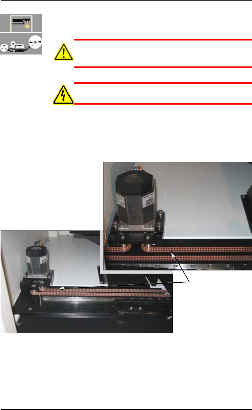
Figure 4-31: Marker Shuttle belt and motor, with Tape Out (A) and
without (B).
3. Test the tension by pulling lightly on the center of the shuttle
belt to the right of the motor. See Figure 4-31. If the belt moves
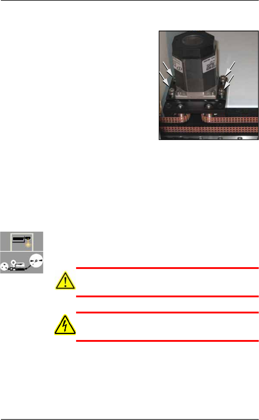
more than 12 mm (0.5 inch) off its path, loosen the four motor
mounting plate screws with a 4 mm hex key (see Figure 4-32),
Test tension here
A
B
■ The Marking Systems and Shuttle ◘ The Shuttle Assembly
PS Series Owner’s Manual 4—37
back
and then push the motor away from the belt until the belt move-
ment is less than 12 mm.
Figure 4-32: Location of four motor mounting plate screws.
3a. If the belt still moves more than 12 mm (0.5 inch), remove it and
cut off as many links as needed to achieve the proper tension.
3b. Replace the belt and tighten the four motor mounting screws.
4. Check the belt sprocket set screws—
4a. Check the belt sprocket set screws and tighten if necessary.
4b. If a sprocket has loosened and is rubbing against the frame,
reposition the sprocket up off the frame and tighten the set
screw.
4c. Reinstall all panels.
Replacing a Shuttle Belt
[Label or Laser Marking, or Tape Out] If the shuttle belt looks worn,
it should be replaced.
CAUTION: Health hazard. The Laser Marking System should be
cleaned as described in Cleaning the Shuttle Assembly on page
4-34 prior to performing work.
WARNING: Electric shock hazard. Shut off the PS System power
(see Turning Off the System on page 4-4) —switch off the main
power switch before removing any panels.
1. Preparation—
1a. Shut off the PS System power and ensure the main power switch
is in the OFF position.
1b. Remove the upper, left Option Bay panel.
2. Relieve belt tension—
Maintenance ■ The Marking Systems and Shuttle
4—38 Data I/O • 981-0424-002
back
2a. Loosen the four motor mounting plate screws. See Figure 4-32
above.
2b. Pull the motor toward yourself to reduce belt tension.
3. Remove the shuttle
3a. Rotate the belt until the shuttle is accessible and unscrew the two
SHCSs (socket-head cap screws) on the inboard side of the car-
riage clamp (2 mm Hex Key).
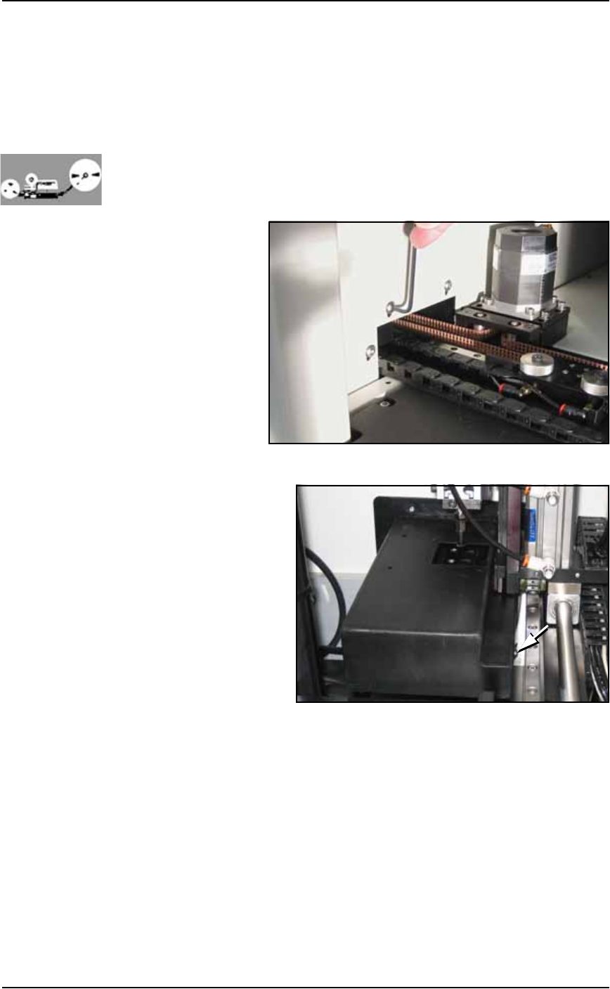
4. [Tape Output only] Remove the belt cover.
4a. Unscrew three SHCSs attaching the Tape Out belt cover to the
Option Bay (1/8 in. Hex Key). See Figure 4-33.
Figure 4-33: Shuttle Belt cover screws [Tape Output only].
4b. Viewing the
belt cover
from the
Taping Sys-
tem Opera-
tor’s view, if
you see two
screws on
the left side
of the cover
skip the next
step.
If you see
two screws
on the right
side of the cover (as shown in the figure above), continue.
4c. (Some assemblies only) Unscrew two SHCSs mounting the Tape
Out PNP head Assembly to the Option Bay for access to more
cover screws (3/16 inch Hex Key). See Figure 4-34. Without dam-
aging the probe, slide the bracket outboard and tip it out of the
way. (Wires are still attached.)