PS288_PS388_PS588_981-0424-002D - 第179页
■ The Marking Systems and Shuttle ◘ The Shuttle Assembly PS Series Owner’s Manual 4—39 back Figure 4-34: Bracket supp ort fasteners for the T ape Output Head Assembly . 4d. Remove tw o screws in th e side of the cov er (…
Maintenance ■ The Marking Systems and Shuttle
4—38 Data I/O • 981-0424-002
back
2a. Loosen the four motor mounting plate screws. See Figure 4-32
above.
2b. Pull the motor toward yourself to reduce belt tension.
3. Remove the shuttle
3a. Rotate the belt until the shuttle is accessible and unscrew the two
SHCSs (socket-head cap screws) on the inboard side of the car-
riage clamp (2 mm Hex Key).
4. [Tape Output only] Remove the belt cover.
4a. Unscrew three SHCSs attaching the Tape Out belt cover to the
Option Bay (1/8 in. Hex Key). See Figure 4-33.
Figure 4-33: Shuttle Belt cover screws [Tape Output only].
4b. Viewing the
belt cover
from the
Taping Sys-
tem Opera-
tor’s view, if
you see two
screws on
the left side
of the cover
skip the next
step.
If you see
two screws
on the right
side of the cover (as shown in the figure above), continue.
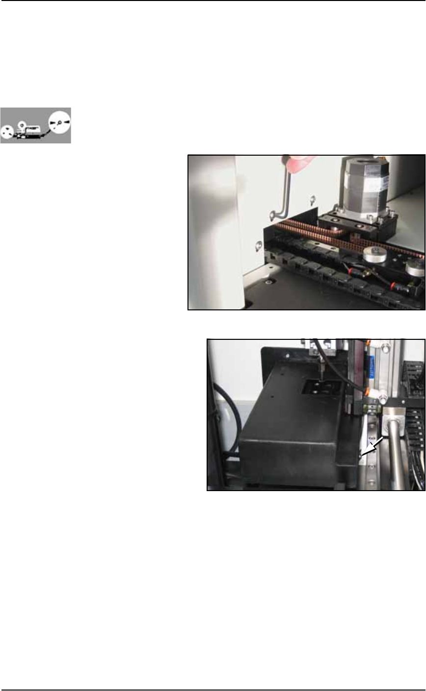
4c. (Some assemblies only) Unscrew two SHCSs mounting the Tape
Out PNP head Assembly to the Option Bay for access to more
cover screws (3/16 inch Hex Key). See Figure 4-34. Without dam-
aging the probe, slide the bracket outboard and tip it out of the
way. (Wires are still attached.)
■ The Marking Systems and Shuttle ◘ The Shuttle Assembly
PS Series Owner’s Manual 4—39
back
Figure 4-34: Bracket support fasteners for the Tape Output Head
Assembly.
4d. Remove two screws in the side of the cover (5/64 inch Hex Key)
and lift off the cover.
5. Remove the belt—
5a. Remove the belt by gently pulling one end completely out of the
shuttle transfer assembly.
6. Install a new belt—
6a. Using the old belt as a template, cut the new belt to the same
length.
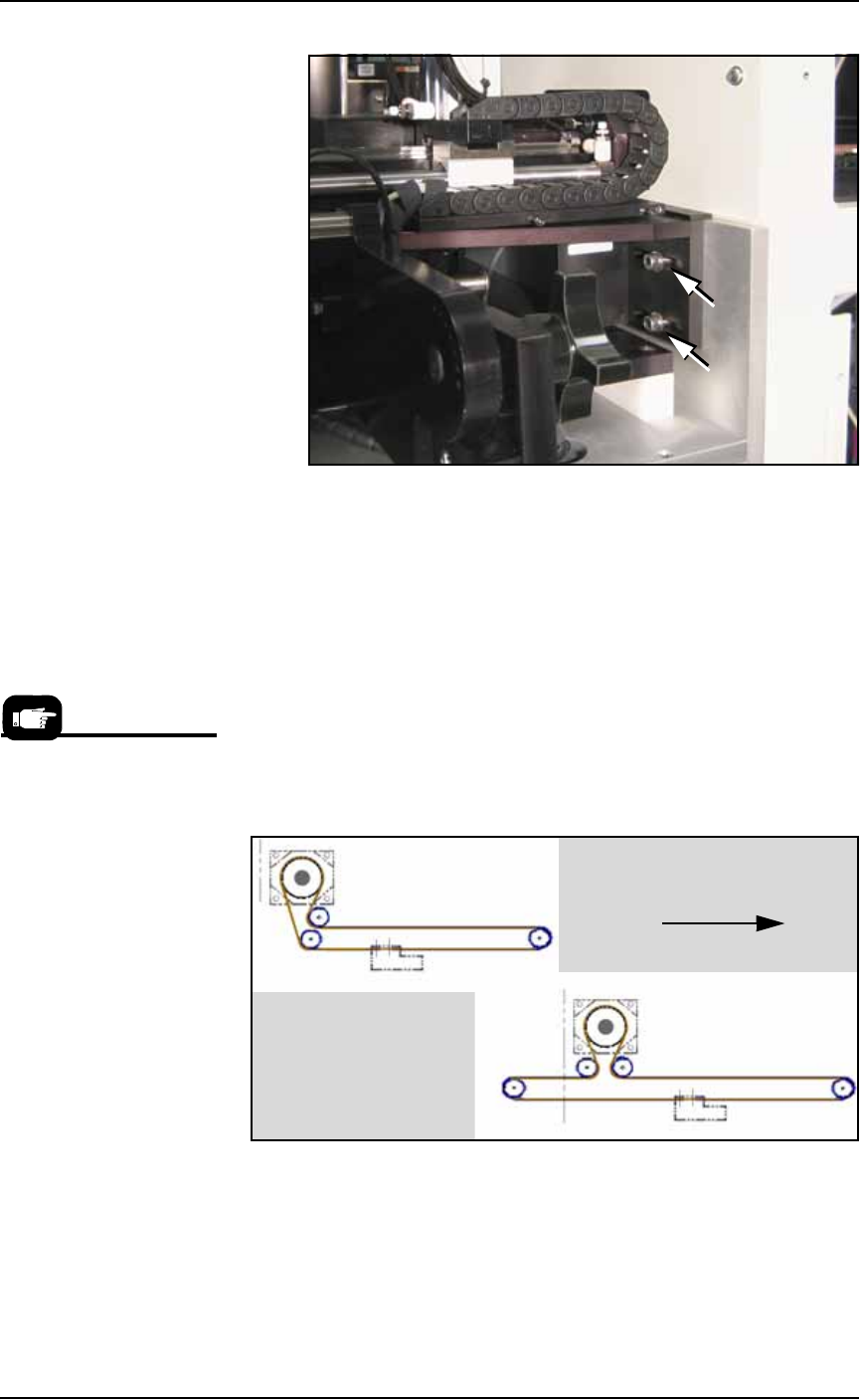
6b. Route the new belt through the shuttle transfer assembly as
shown in Figure 4-35. Make sure all sprocket teeth mesh with
the holes in the belt.
Figure 4-35: The shuttle belt routing for systems with a marking
option, with and without the Tape Output option.
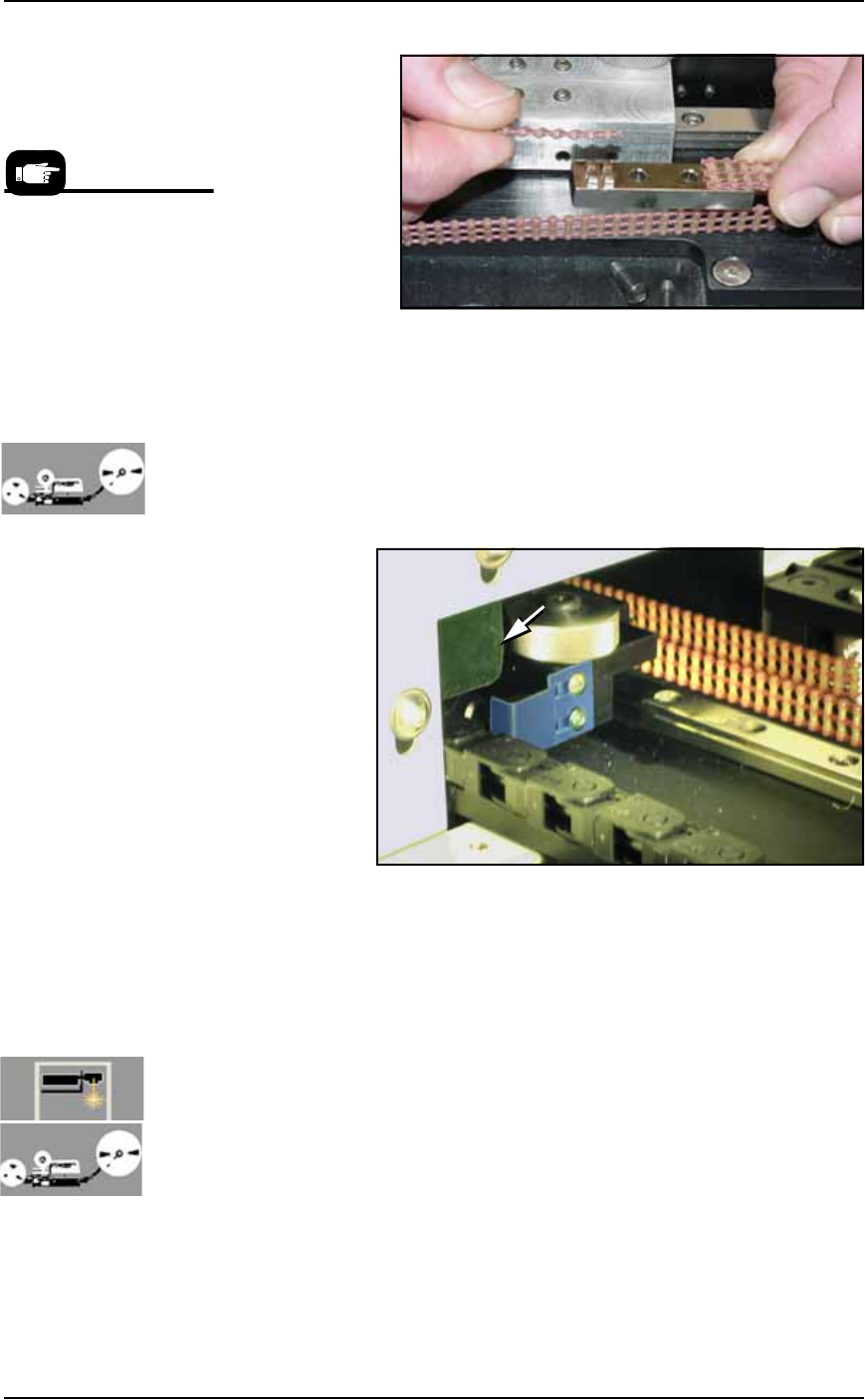
6c. Connect the belt ends to the shuttle clamp as shown in Figure
4-36. Ensure that the teeth on the shuttle clamp are engaged with
the holes on the belt. If the belt is too long, cut off excess length.
Re-attach the shuttle clamp to the shuttle.
Data I/O Part Number for
the Shuttle Belt is
264-0009-001 or higher:
• 1.8 M (6 feet) for Option
Bay with Tape Output Mod-
ule.
• 1.5 M (5 feet) for Option
Bay with Marker only (no
Tape Output).
Toward PS Machine operator
Without Tape Output
With Tape Output
Maintenance ■ The Marking Systems and Shuttle
4—40 Data I/O • 981-0424-002
back
Figure 4-36: Clamping the belt to the shuttle.
6d. Check belt tension and adjust if necessary as described in Adjust-
ing Shuttle Belt Tension on page 4-36.
7. Reinstall—
7a. [Tape Output only] Reinstall the belt cover by installing the
three screws inside the Option Bay (before the other two).
Ensure that the shuttle flag shown in the figure below does not
hit the belt cover flange when it moves past the cover.
Figure 4-37: The shuttle flag (tinted blue here) must clear the flange on
the belt cover (arrow).
7b. Reinstall the two other cover screws.
7c. (If applicable) reinstall the Tape Output Head Assembly sup-
port.
7d. Reinstall the Option Bay panel.
Cleaning the Shuttle O-Rings
[Laser Marking and Tape Output only] The Shuttles used for Laser
Marking and for Tape Output use O-ring seals. Dirty seals may leak
enough air that devices fall from the shuttle. Cleaning intervals
depend on amount of use.
To clean the seals:
1. Move the shuttle to the PS work area—
Prior to reinstalling the
Option Bay cabinet panels,
you may wish to clean or
replace the shuttle O-rings.
See step 2 of Cleaning the
Shuttle O-Rings on page
4-40 or Replacing the
Shuttle O-Rings on page
4-41.