PS288_PS388_PS588_981-0424-002D - 第180页
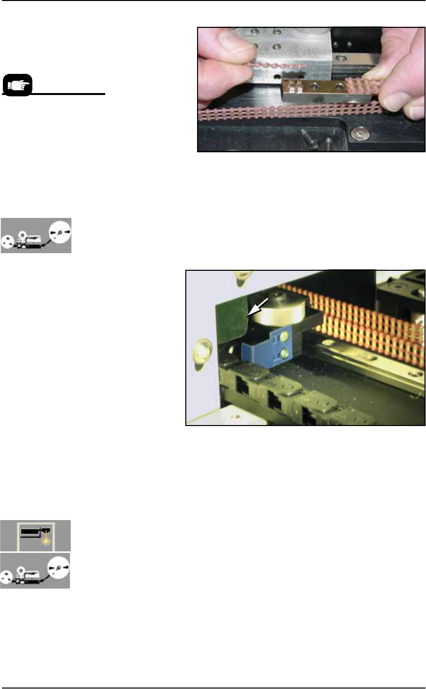
Maintenance ■ The Marking Systems and Shuttle 4—40 Data I/O • 981-0424 -002 back Figure 4-36: Clamping the belt to the shuttle. 6d. Check belt tension and adjust if necessary as described in Adjust- ing Shuttle Belt T en…
■ The Marking Systems and Shuttle ◘ The Shuttle Assembly
PS Series Owner’s Manual 4—39
back
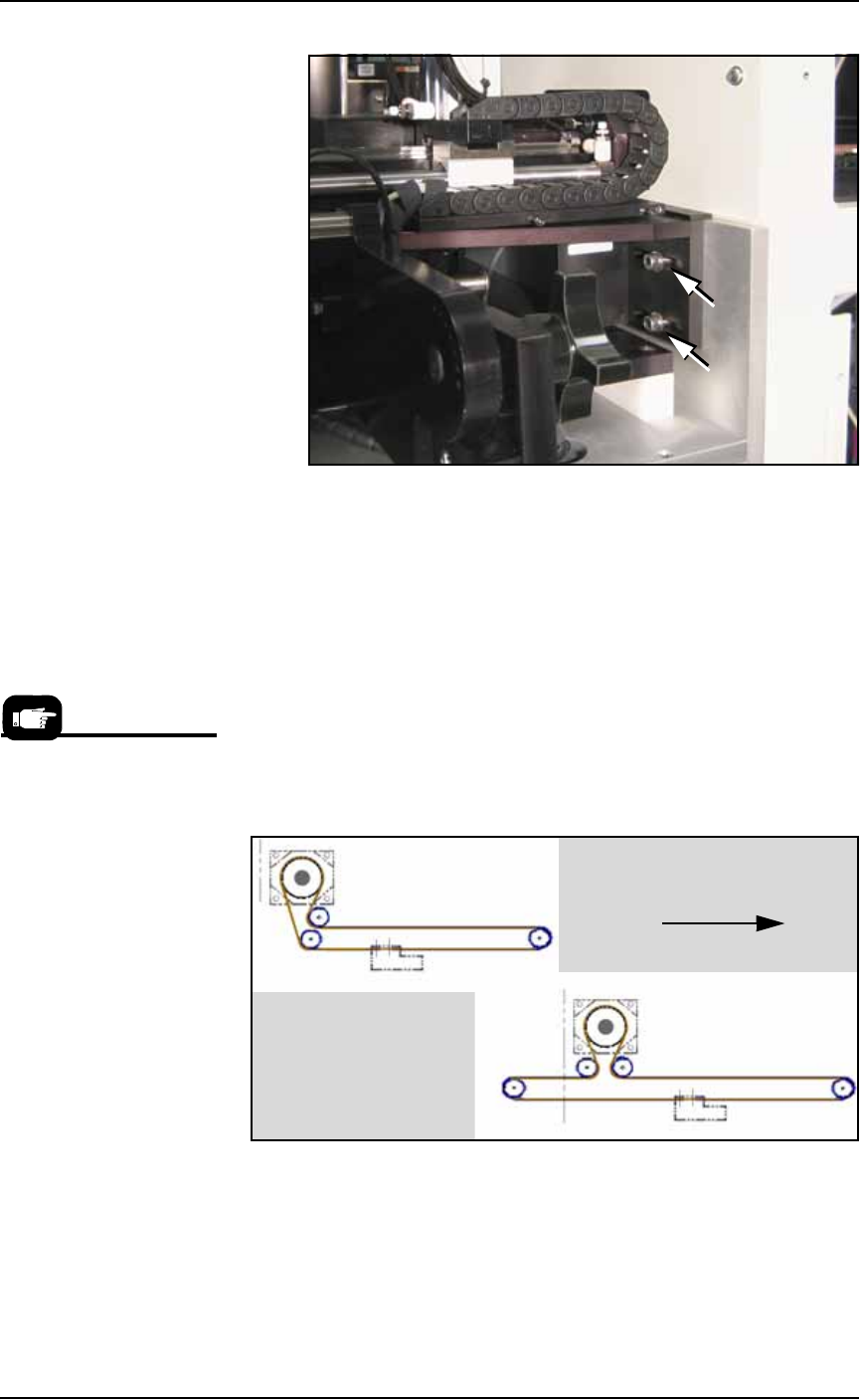
Figure 4-34: Bracket support fasteners for the Tape Output Head
Assembly.
4d. Remove two screws in the side of the cover (5/64 inch Hex Key)
and lift off the cover.
5. Remove the belt—
5a. Remove the belt by gently pulling one end completely out of the
shuttle transfer assembly.
6. Install a new belt—
6a. Using the old belt as a template, cut the new belt to the same
length.
6b. Route the new belt through the shuttle transfer assembly as
shown in Figure 4-35. Make sure all sprocket teeth mesh with
the holes in the belt.
Figure 4-35: The shuttle belt routing for systems with a marking
option, with and without the Tape Output option.
6c. Connect the belt ends to the shuttle clamp as shown in Figure
4-36. Ensure that the teeth on the shuttle clamp are engaged with
the holes on the belt. If the belt is too long, cut off excess length.
Re-attach the shuttle clamp to the shuttle.
Data I/O Part Number for
the Shuttle Belt is
264-0009-001 or higher:
• 1.8 M (6 feet) for Option
Bay with Tape Output Mod-
ule.
• 1.5 M (5 feet) for Option
Bay with Marker only (no
Tape Output).
Toward PS Machine operator
Without Tape Output
With Tape Output
Maintenance ■ The Marking Systems and Shuttle
4—40 Data I/O • 981-0424-002
back
Figure 4-36: Clamping the belt to the shuttle.
6d. Check belt tension and adjust if necessary as described in Adjust-
ing Shuttle Belt Tension on page 4-36.
7. Reinstall—
7a. [Tape Output only] Reinstall the belt cover by installing the
three screws inside the Option Bay (before the other two).
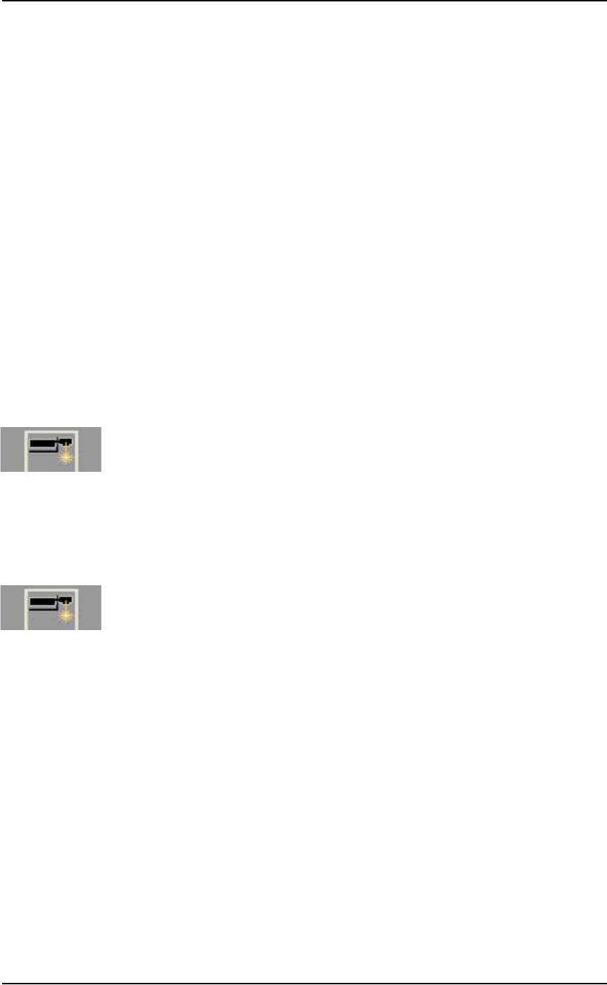
Ensure that the shuttle flag shown in the figure below does not
hit the belt cover flange when it moves past the cover.
Figure 4-37: The shuttle flag (tinted blue here) must clear the flange on
the belt cover (arrow).
7b. Reinstall the two other cover screws.
7c. (If applicable) reinstall the Tape Output Head Assembly sup-
port.
7d. Reinstall the Option Bay panel.
Cleaning the Shuttle O-Rings
[Laser Marking and Tape Output only] The Shuttles used for Laser
Marking and for Tape Output use O-ring seals. Dirty seals may leak
enough air that devices fall from the shuttle. Cleaning intervals
depend on amount of use.
To clean the seals:
1. Move the shuttle to the PS work area—
Prior to reinstalling the
Option Bay cabinet panels,
you may wish to clean or
replace the shuttle O-rings.
See step 2 of Cleaning the
Shuttle O-Rings on page
4-40 or Replacing the
Shuttle O-Rings on page
4-41.
■ The Marking Systems and Shuttle ◘ Laser Marking Filters
PS Series Owner’s Manual 4—41
back
1a. (This requires a Laser Marker to be selected in your
winAH400.ini
file.)Open TaskLink and select a task with the
Laser Marker option and click Run. Follow on-screen dialogs.
1b. After the AH500 Application opens, click Start, then System.
You may need to enter a password.
1c. Click Shuttle/Options.
1d. Click the Go button adjacent to the PED 2, Load Pos.
2. Cleaning the O-rings
2a. Push the Emergency-Stop.
2b. Open a workspace door and wipe the O-rings with a damp
cloth. (Don’t use alcohols or solvents.)
Replacing the Shuttle O-Rings
To replace the shuttle O-rings:
1. Follow the steps to clean the O-rings (above).
2. Pull the O-ring off each shuttle cup nipple and push the new
O-ring on. Ensure that the O-ring is higher than the metal nip-
ple.
Laser Marking Filters
[Laser Marking only] The Laser Marking System has a total of five
filters spread among two locations. In some PS Machines with Laser
Marking, there is a Laser Computer computer— it has a small air
filter requiring minimal care. And on all models with Laser Marking
have a fume extractor with four filters stacked inside one extractor
housing. The fume extractor filters require special safety precautions
as noted in the following instructions. The fume extractor and the
laser computer are both inside the Option Bay.
Removing the Fume Extractor Filters
[Laser Marking only] The Handler Computer software monitors the
air flow sensor on the laser filter system. If the sensor detects low air
flow, an error message is displayed on the PS Monitor:
Insufficient airflow at laser filter.
Verify that the filter is turned on.
Service might be required.
When this error message (above) displays, the laser system will mark
up to ten more devices (as defined in the
winAH400.ini
file) before
the message displays again.