PS288_PS388_PS588_981-0424-002D - 第183页
■ The Marking Systems and Shuttle ◘ Laser Marking Filters PS Series Owner’s Manual 4—43 back 1b. If the machine also has a T ape Output Module, screw the feet on the black legs up so they don’ t contact the floor . 1c. R…
Maintenance ■ The Marking Systems and Shuttle
4—42 Data I/O • 981-0424-002
back
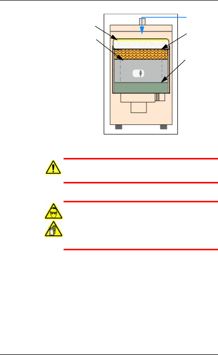
Figure 4-38: Fumex Laser Marker vacuum filter stacking order.
WARNING: Health hazard. Failure to replace the laser vacuum
filters at the required intervals could create a hazardous operat-
ing environment.
WARNING: Hazardous Materials. This procedure involves expo-
sure to hazardous by-products from the laser marking process.
Some device material may be carcinogenic.
Perform the following procedure only if you have successfully
completed a training class regarding laser etching processes or
handling hazardous materials.
Tools Required
• sealable plastic bag (approximately. 1 cu. M)
• protective gloves and goggles
• Optional, a particle (dust) mask
•Hex Keys
To replace the Fumex filters:
1. Preparation—
1a. Shut off PS System power and ensure the main power switch is
in the OFF position. See Turning Off the System on page 4-4.
Air flow
Pleated filter
Carbon filter
Pre-filter
HEPA filter
■ The Marking Systems and Shuttle ◘ Laser Marking Filters
PS Series Owner’s Manual 4—43
back
1b. If the machine also has a Tape Output Module, screw the feet on
the black legs up so they don’t contact the floor.
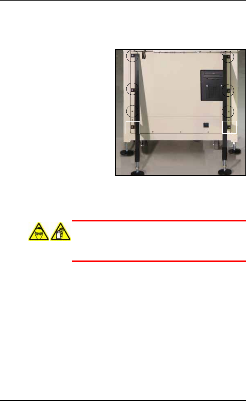
1c. Remove lower back laser housing panel from the laser enclosure
by removing the six or eight screws—depending on whether a
Tape Output Module is installed. See Figure 4-39.
Figure 4-39: The lower back laser housing panel screw locations,
shown here with legs for the optional Tape Output module.
1d. Remove side laser housing panel by removing the four screws.
See Figure 4-40.
WARNING: Hazardous materials. Wear safety goggles and dis-
posable protective gloves. Do not clean the laser vacuum filters by
blowing with compressed air, shaking, or using any method that
allows the particulate trapped by the filters to be released into
the work environment.
Maintenance ■ The Marking Systems and Shuttle
4—44 Data I/O • 981-0424-002
back
Figure 4-40: The lower, side laser housing panel and screw locations.
1e. Put on the disposable protective gloves and the safety goggles.
Open the sealable plastic bag.
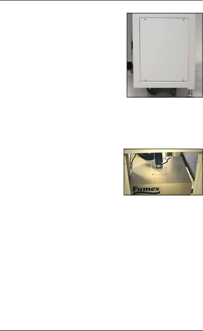
2. Detach vacuum hose—
2a. Loosen the clamp holding the vacuum hose to the extractor top
and detach the vacuum hose from the extractor top. See Figure
4-41.
Figure 4-41: The Vacuum hose clamp.
3. Release the four spring clips (one on each side except on early
models) securing the extractor top to the filter system. Pull the
extractor top up hard to release it.