PS288_PS388_PS588_981-0424-002D - 第188页
Maintenance ■ Handler Computer 4—48 Data I/O • 981-0424 -002 back Handler Computer The main PS Machine computer , or Handler Computer , is accessed from the front of the machine, in the low er left corner , and requires …
■ The Marking Systems and Shuttle ◘ Laser Marking Filters
PS Series Owner’s Manual 4—47
back
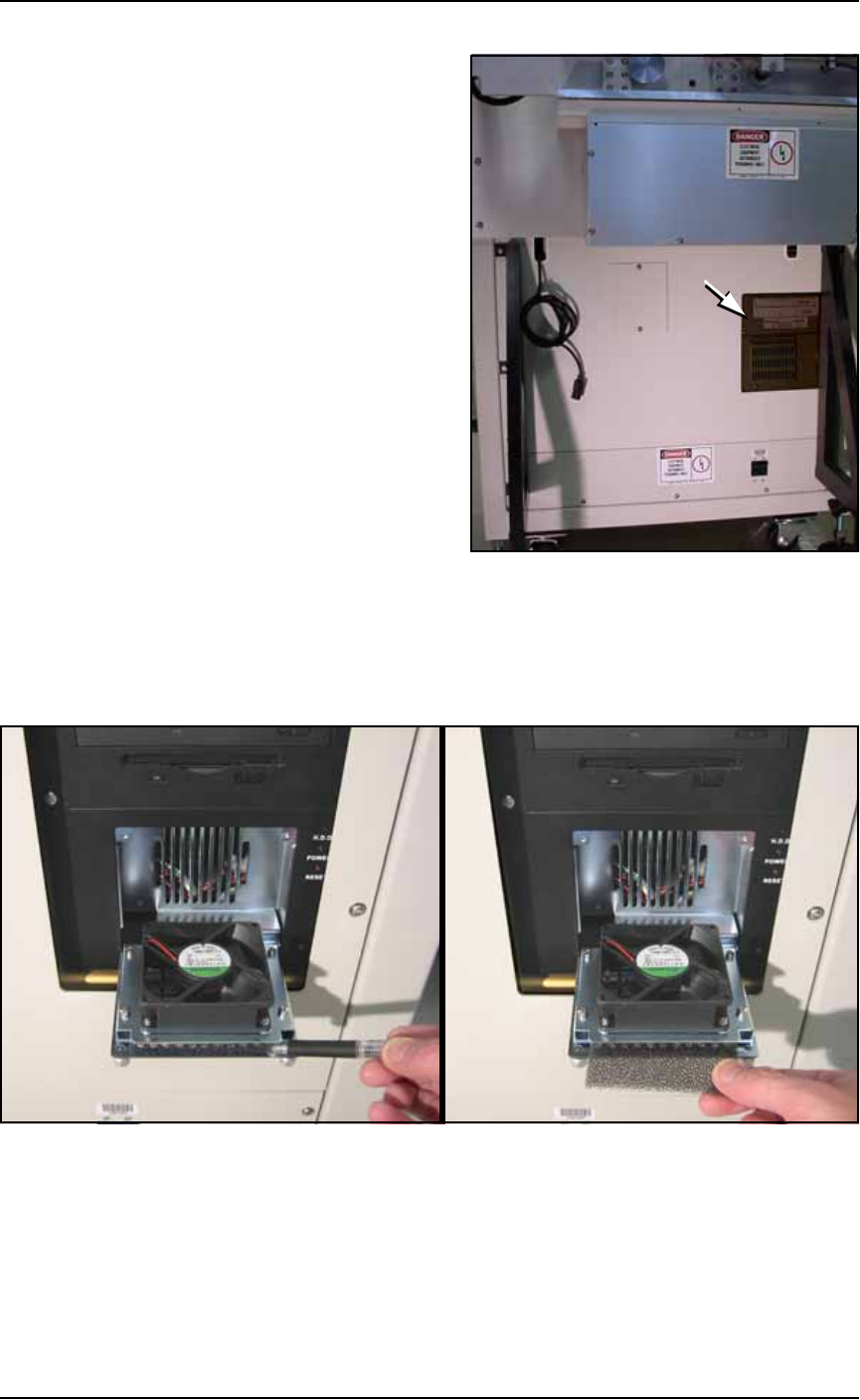
Figure 4-44: The location of Laser Computer filter on the back of the
Laser Marker frame. (Some models only.)
To remove the Laser Computer air filter:
1. Unscrew the two captive thumb screws on the filter cover and
open the cover door. See Figure 4-45.
Figure 4-45: After opening the Laser Marker Computer filter cover,
drag the filter out with a pen or pencil. (Early filter covers are not
hinged.)
2. Remove the old air filter. Clean or replace with a new air filter as
necessary.
3. Close the filter cover and screw in the thumb screws.
Maintenance ■ Handler Computer
4—48 Data I/O • 981-0424-002
back
Handler Computer
The main PS Machine computer, or Handler Computer, is accessed
from the front of the machine, in the lower left corner, and requires
little maintenance.
Handler Computer Air Filter
The Handler Computer has a air filter that requires period cleaning
or replacing.
To remove the air filter:
1. Open the front panel by unlocking (if applicable) and twisting
the key knob right 1/4 turn.
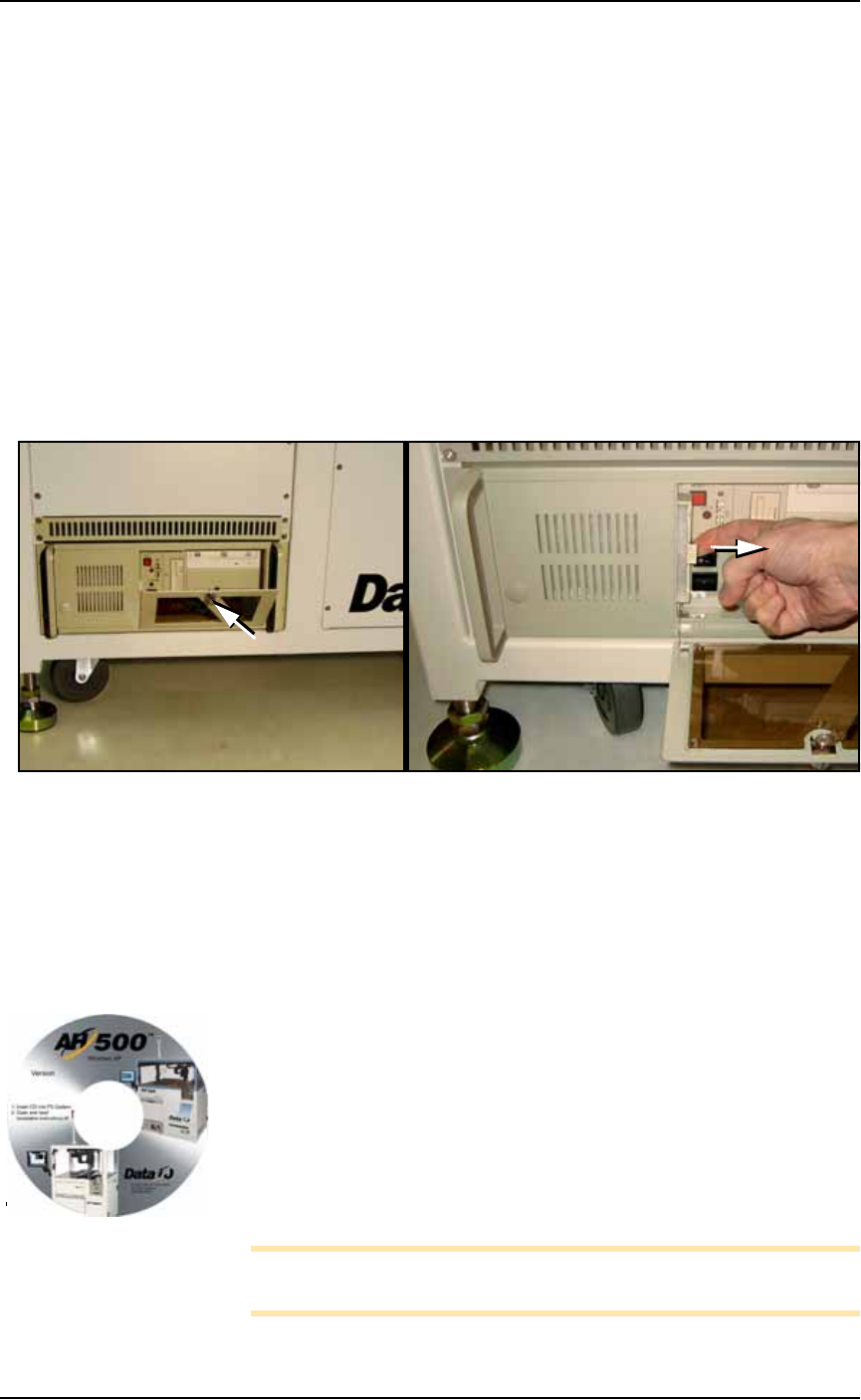
Figure 4-46: The Handler Computer door and knob (A) and filter (B).
2. Pull out the filter to the right as shown in Figure 4-46. The fil-
ter should be white. Clean or replace as necessary.
Installing AH500 Software Updates
AH500 Software Updates are periodically published with improve-
ments. Delivery depends on contract options.
To install new AH500 Updates on the PS Handler Computer:
1. Create a backup copy of the
winAH500.ini
file (on your Handler
computer).
2. Insert the AH500 CD and follow instructions in the
Installa-
tion Instructions.rtf
file.
3. Rename your.ini file again back to
winAH500.ini
(replacing the
new.ini file) to keep your settings.
Note: Updating TaskLink is a different CD. For more TaskLink
information, see TaskLink’s on-screen Help.
A
B
Your CD looks similar to
this.
■ The Vision System ◘ Inspecting the Vision Camera
PS Series Owner’s Manual 4—49
back
The Vision System
The vision system provides for angular correction up to 30 degrees
for devices on the probe before they are placed in the programming
socket. This angular correction is performed to reduce the likelihood
of device damage from improper insertion.
Inspecting the Vision Camera
WARNING: Electric shock hazard. The PS Machine operates at
high voltage. Switch off the PS System main power switch before
opening any access doors or removing any cabinet panels. See
Turning Off the System on page 4-4.
1. Preparation—
1a. Shut off the PS System power and ensure the main power switch
is in the OFF position. For more information see Turning Off the
System on page 4-4.
1b. Open the right access door.
CAUTION: Data could be rendered useless. When tightening fas-
teners, do not move the camera or the Vision System will need
recalibration (page 4-50) and all your vision files will be need to
be recreated (page 3-34).
2. Check fasteners—
2a. Check the three mounting screws in the camera bracket and
tighten if necessary with a 1/8 inch Hex Key. See Figure 4-47.
2b. Check the two mounting screws in the camera lens body and
tighten if necessary with a 2 mm Hex Key.