PS288_PS388_PS588_981-0424-002D - 第193页
■ The Vision System ◘ Calibrating The Vision System PS Series Owner’s Manual 4—53 back Part 1–Calibrating Cognex V ision with Checkerboard Ta r g e t CAUTION: After r ecalibrating your vision system, all existing .vpp fi…
Maintenance ■ The Vision System
4—52 Data I/O • 981-0424-002
back
you to do so. Use extreme caution and do not touch any electronic
equipment except as directed.
5c. Open the right access door.
5d. Without touching any live electronics, adjust the camera lens as
follows:
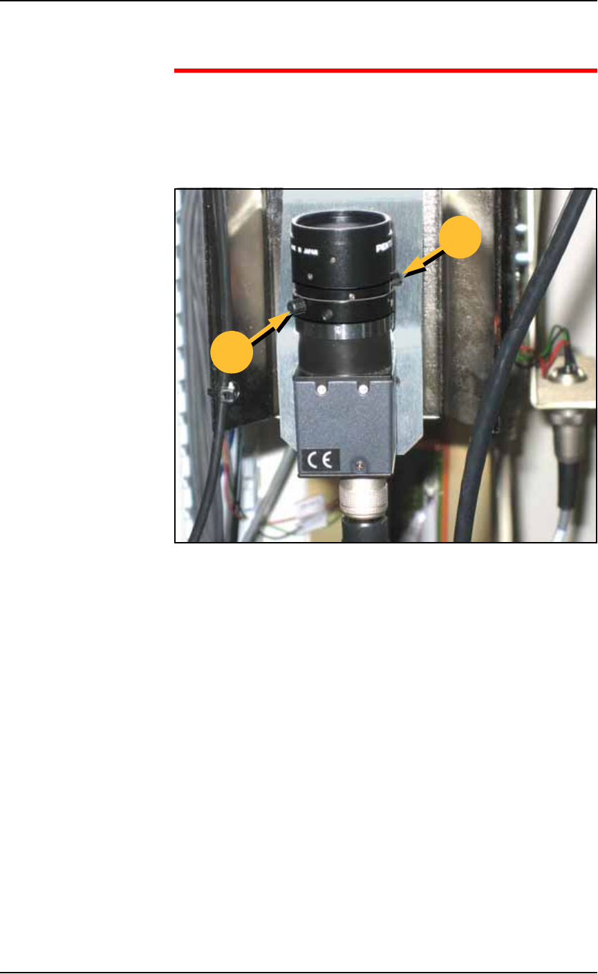
5d.1) Loosen the lower of the two ring locking screws (by
hand). See figure.
Figure 4-49: Roughing-in camera lens adjustment by hand. 'B' is the
locking screw and adjustment ring for the Brightness. 'F' is the locking
screw and adjustment ring for the Focus.
5d.2) Turn the ring to lighten or darken the image.
5d.3) Tighten the ring (by hand).
5d.4) Loosen the upper ring locking screw.
5d.5) Turn the ring to adjust focus.
5d.6) Tighten the ring.
5e. Close the Live Video window.
5f. Click Exit.
6. Finish getting a good picture—
6a. Click Exit again to get back to the Gantry Window.
6b. Replace the device into its original location.
6c. Click the Vision button and visually check that the picture is
good quality again.
B
F
■ The Vision System ◘ Calibrating The Vision System
PS Series Owner’s Manual 4—53
back
Part 1–Calibrating Cognex Vision with Checkerboard
Target
CAUTION: After recalibrating your vision system, all existing .vpp
files (Vision and Package files) will need to be retaught.
To calibrate the Vision System:
1. Preparation—
1a. Create a good Vision System picture. See the previous heading
on page 4-51.
1b. Click the Vacuum on button.
1c. Place the calibration target by hand so that the checkerboard
pattern is facing downward, towards the camera.
2. Verify settings—
2a. Navigate to the Camera Calibration Tab (System > Gantry > Go-to
tab > Go-To-Vision button > Calibration tab) and then click the Cal-
ibrate tab.
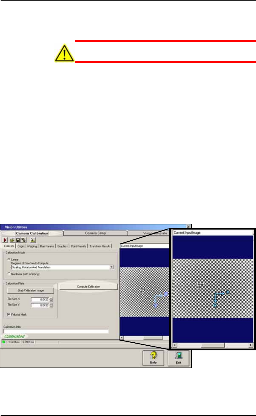
2b. Verify that:
• the Calibration Mode is set to Scaling, Rotation and Translation,
and
• Tile Size X & Y are 0.0433, and
• Fiducial Mark is checked. See the figure below.
You can position the blue axis by selecting Current.CalibrationIm-
age from the drop-down list above the image window, and drag-
ging the axis to the new location.
Figure 4-50: The Vision Utilities Dialog with Camera Calibration Tab
selected, and then Calibrate tab selected. In this image, the Compute
Calibration function has finished successfully.
Maintenance ■ The Vision System
4—54 Data I/O • 981-0424-002
back
3. Computing Calibration—
3a. Select Grab Calibration Image.
3b. Perform calibration by selecting Compute Calibration.
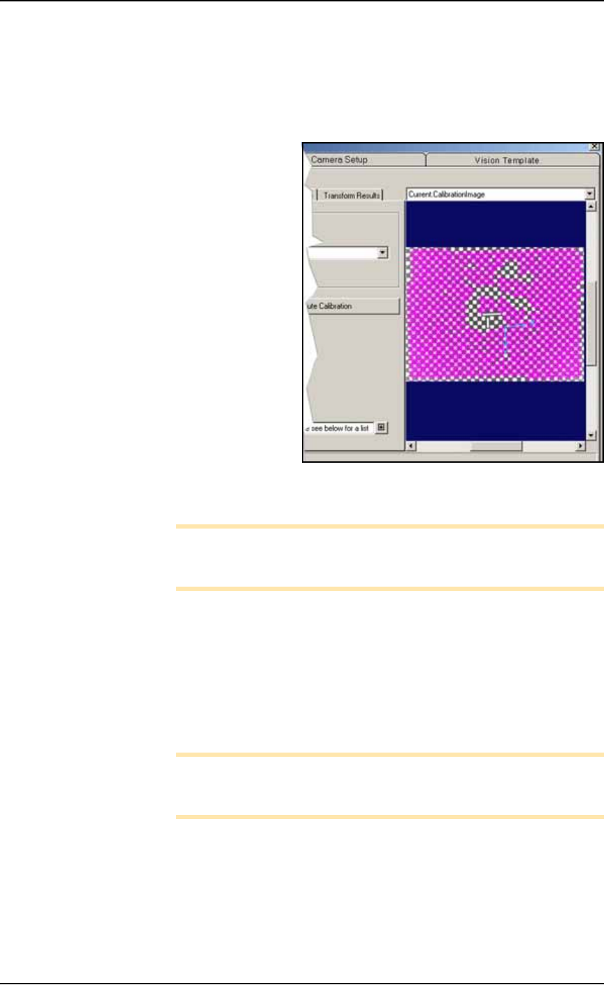
3c. Select Current.CalibrationImage from the pull-down list and ver-
ify that the majority of the picture is pink. The pink color means
those tiles were used for calibration.
Figure 4-51: This resulting calibration image shows plenty of pink
meaning more than enough tiles were used for calibration.
Note: Ensure no error messages display in the Calibration Info bar
at the bottom of the screen. If error information exists, apply the
message recommendation, and try to calibrate again.
4. Assessing results—
4a. If successful, the green Calibrated message displays in the
lower-left corner of the calibration screen. Save the current
image to the
CameraCalibration.vpp
file by clicking the Save
button, select
CameraCalibration.vpp
, and click Save. When
asked to replace the existing file click OK. Note that the
Camera-
Calibration.vpp
file must be saved from the Camera Calibra-
tion tab.
Note: If you accidentally replace the wrong file, there is folder
named Backup with the original files in them. Copy the desired
backup file to the current working directory.
4b. If NOT successful (there is not much pink color), then repeat
from Step 3 above or make Electronic Vision Adjustments as fol-
lows:
4b.1) Click the Camera Setup tab.
4b.2) Click Electronic Mode (lightning bolt)
4b.3) Adjust the Brightness and Contrast sliders.