PS288_PS388_PS588_981-0424-002D - 第196页
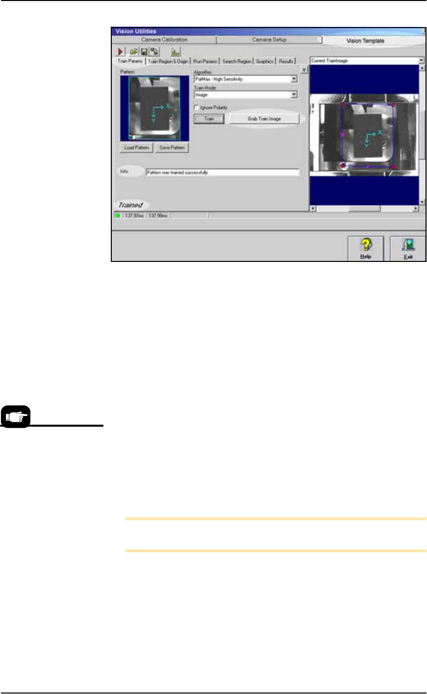
Maintenance ■ T he Vision System 4—56 Data I/O • 981-0424 -002 back Figure 4-52: The Vision Utilities Dialog wit h Vision T emplate T ab selected. Af te r clicking the Grab T r ain Image button, the Info field display s …

■ The Vision System ◘ Calibrating The Vision System
PS Series Owner’s Manual 4—55
back
4b.4) Click the Camera Calibration tab and repeat from
Step 3 Computing Calibration.
5. Finish Part 1—
5a. Click Exit.
5b. Remove the checkerboard target by hand.
Part 2—Updating Vision File Parameters (and then the
Vision File itself)
1. Preparation—
1a. In the Gantry Window, pick up device by moving the probe to
socket 1 of a programmer and right-clicking.
1b. Ensure that the device is centered on the probe.
1c. Click the Go To tab. Click the Go To Vision button.
2. Update vision parameters—
2a. Click the Calibration button to open the Vision Utilities dialog.
2b. Click the Vision Template tab.
2c. Click the Train Parms tab.
2d. From the Algorithm drop-down select PatMax – High Sensitivity.
2e. Ensure that Ignore Polarity is unchecked.
2f. Click Grab Train Image.
2g. Select Current.TrainImage from pull-down menu above the right
camera picture.
2h. Adjust origin of the turquoise X-Y axes as close as possible to the
center of the device. Position the axes by clicking it and drag-
ging.
2i. Adjust the blue search-area rectangle to look similar to the one
in the figure below (roughly: just under the size of the opener).
Click a rectangle handle to resize it.
Maintenance ■ The Vision System
4—56 Data I/O • 981-0424-002
back
Figure 4-52: The Vision Utilities Dialog with Vision Template Tab
selected. After clicking the Grab Train Image button, the Info field
displays results.
3. Training the vision—
3a. Click the Grab Train Image button. Recheck that the X-Y axes
symbol is still centered. If not, adjust it and then click Grab Train
Image again.
3b. Click the Train button.
3c. If the Train function was successful, Trained displays in the
lower-left corner of the screen and no error messages display in
the Info field. If an info message does appear, either create a bet-
ter vision system picture (Getting a Good Picture: Vision System on
page 4-51), or adjust the quality of the current image with bright-
ness/contrast.
Otherwise, if the info says successful click Save. Select your
device-specific vision file (such as TSOP48.VPP) and click Save.
Also, save this image as the
VisionTemplate.vpp
file— Save >
select VisionTemplate.vpp > Save.
3d. Click Exit.
Note: The VisionTemplate.vpp file must be updated every time the
system is recalibrated.
Reteach the Vision Inspection Parameters
1. Teach the Parameters—
1a. Navigate to System > Gantry > Vision System (if you are not
already there).
1b. Click Setup.
VisionTemplate.vpp is the
vision template for all new
vision files. To use it, copy,
paste, and rename it (such
as TSOP48.vpp) when cre-
ating vision files for new
jobs.
■ The Vision System ◘ Calibrating The Vision System
PS Series Owner’s Manual 4—57
back
1c. Click a handle of the blue rectangle and adjust the search region
to match the device boundary.
1d. Click Teach.
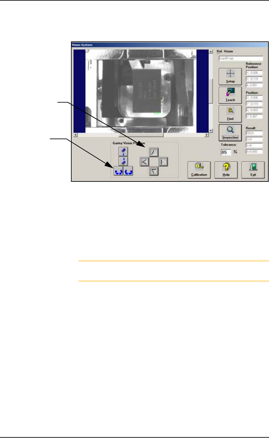
Figure 4-53: Testing the vision inspection with the Gantry Vision
Position buttons and rechecking the Results.
2. Test—
2a. Test the vision inspection by clicking Inspection and then verify-
ing that the results are
PASS, X = 0, Y = 0,
and
A = 0.00
.
2b. Further test by clicking the position arrows and probe rotation
buttons and then clicking Inspection and verifying the move-
ment in the Results fields. (This change is not saved.)
Note: Remember: prior to running existing jobs, reteach the vision
file.
Navigation Arrows:
each click moves the
head 0.010 inches.
Rotation buttons:
each click rotates the
probe 1 degree.