PS288_PS388_PS588_981-0424-002D - 第197页
■ The Vision System ◘ Calibrating The Vision System PS Series Owner’s Manual 4—57 back 1c. Click a handle of the blue rect angle and adjust the search region to match the device boundary . 1d. Click Te a c h . Figure 4-5…
Maintenance ■ The Vision System
4—56 Data I/O • 981-0424-002
back
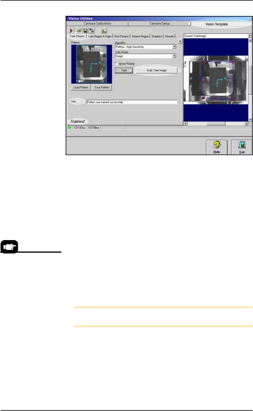
Figure 4-52: The Vision Utilities Dialog with Vision Template Tab
selected. After clicking the Grab Train Image button, the Info field
displays results.
3. Training the vision—
3a. Click the Grab Train Image button. Recheck that the X-Y axes
symbol is still centered. If not, adjust it and then click Grab Train
Image again.
3b. Click the Train button.
3c. If the Train function was successful, Trained displays in the
lower-left corner of the screen and no error messages display in
the Info field. If an info message does appear, either create a bet-
ter vision system picture (Getting a Good Picture: Vision System on
page 4-51), or adjust the quality of the current image with bright-
ness/contrast.
Otherwise, if the info says successful click Save. Select your
device-specific vision file (such as TSOP48.VPP) and click Save.
Also, save this image as the
VisionTemplate.vpp
file— Save >
select VisionTemplate.vpp > Save.
3d. Click Exit.
Note: The VisionTemplate.vpp file must be updated every time the
system is recalibrated.
Reteach the Vision Inspection Parameters
1. Teach the Parameters—
1a. Navigate to System > Gantry > Vision System (if you are not
already there).
1b. Click Setup.
VisionTemplate.vpp is the
vision template for all new
vision files. To use it, copy,
paste, and rename it (such
as TSOP48.vpp) when cre-
ating vision files for new
jobs.
■ The Vision System ◘ Calibrating The Vision System
PS Series Owner’s Manual 4—57
back
1c. Click a handle of the blue rectangle and adjust the search region
to match the device boundary.
1d. Click Teach.
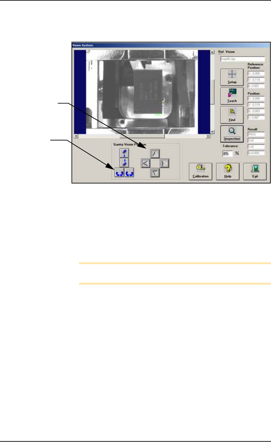
Figure 4-53: Testing the vision inspection with the Gantry Vision
Position buttons and rechecking the Results.
2. Test—
2a. Test the vision inspection by clicking Inspection and then verify-
ing that the results are
PASS, X = 0, Y = 0,
and
A = 0.00
.
2b. Further test by clicking the position arrows and probe rotation
buttons and then clicking Inspection and verifying the move-
ment in the Results fields. (This change is not saved.)
Note: Remember: prior to running existing jobs, reteach the vision
file.
Navigation Arrows:
each click moves the
head 0.010 inches.
Rotation buttons:
each click rotates the
probe 1 degree.

Maintenance ■ Troubleshooting
4—58 Data I/O • 981-0424-002
back
Troubleshooting
This section contains solutions to problems that may arise during
operation of the PS System.
Troubleshooting for the Tape Output System is covered in a separate
heading; see Troubleshooting the Tape Output System on page 4-74.
Common Error Messages
Restarting after Trouble
If the AH500 Software closes, locks up, or experiences some trouble
that qualifies as a crash, then the PS Machine power must be
switched off for 20 seconds prior to restarting the software. This is
required to reset internal amplifiers.
Error Message Resolution
“E-STOP
ACTIVATED”
but . . .
the
OK button is grayed
out in error message
(unavailable)
• Check that both E-Stop buttons are released.
• Check that all six safety shields are closed.
• Check that the Option Bay safety shield is closed.
• Check the LED sensors on the safety shields. Yellow LED indicates the
sensor is not detecting that the safety shield is properly closed. Re-close
safety shield.
• Once condition is solved, the OK button is enabled. Click
OK.
TRAY NOT PRESENT Conditions: You swapped input tray but the PS does not detect the tray and
when you click Run, you get error message Tray Not Present.
• Re-install the tray.
• If the tray is still not detected, remove the tray and place a finger over tray
present sensor.
–If sensor is working, tray outline appears. Re-install tray.
–If sensor is not working, the tray outline does not appear. In this case,
contact Data I/O Customer Support or a local Data I/O approved ser-
vice representative.
Z MOTION ERROR 800:
LIMIT EXCEEDED ON
AXIS 2
Conditions: A Red ERROR box appears in bottom right corner of the PS Machine
Monitor.
Call the Service Technician.
ERROR: TAPE OUT • If a device is jammed in the Tape Output system, clear it. Click the reset
button on Tape Output System. Then click
OK on PS Machine Monitor.
• If above doesn't work, call the Service Technician.
MAIN AIR OFF • Check that the main input air valve is in the ON position.
• Check that the main air hose is connected.
• Check that the air pressure is within the required range (green LED read-
out instead of red on 2009 models and later.)
• Call the Service Technician.
VACUUM ERROR Call the Service Technician.