PS288_PS388_PS588_981-0424-002D - 第205页
■ Trouble shooting ◘ Air Pressure Problems PS Series Owner’s Manual 4—65 back #39 100 MSEC, TRA YS & TUBES, V ACUUM SUCKUP TIME A T CUPS DURING PICKUP T rouble with the PNP Head. T wo serv o-amplifiers (inside …
Maintenance ■ Troubleshooting
4—64 Data I/O • 981-0424-002
back
2a. Click the black DISABLED button. The socket image changes to
black and the programmer is disabled.
2b. Repeat for all sockets on the target programmer.
For more information on changing programmer or socket status,
see Changing Programmer Status on page 3-25.
Pick and Place Problems
Devices are not being placed into sockets or output media accu-
rately.
The PNP Head does not center on the devices.
Check that the probe is not bent.
(Models prior to Feb. 2009) Check that the break-away probe tip
is snapped fully into place.
Check that fasteners on the head, gantry, and camera are tight.
See Inspecting Gantry Parts on page 4-24 and Inspecting the Vision
Camera on page 4-49.
Reteach the Vision file. See Teaching the Reference Vision File on
page 3-34.
Calibrate the Vision System. See Calibrating The Vision System on
page 4-50.
Adjust the X-, Y-, and Z-axis positions using the adjustment
arrows on the Gantry Window.
The Probe is dropping devices.
Clean or replace the rubber Probe Tips. See PNP Probe on page
4-12.
Clean the vacuum filter or silencer. See Vacuum Generator Filters
and Silencers on page 4-15.
Check that the main input air pressure is 5.5 ±0.7 Bar
(80 ±10 PSI). Refer to Connecting Air on page 2-2.
[PS288, PS388 and Optima Programmers only on PS588] If the
problem looks like it could be caused by the sockets: reset the
Socket Opener air pressure at the Power Panel. Pressure must be
in the correct range for your PS Machine and adapter. See
Adjusting the Socket Actuator Air Pressure on page 4-8.
Probe attempts to pick a device twice even though it picked up
the device the first time.
The Vacuum sensor may need calibrating. See PNP Head Vacuum
Generator Sensor on page 4-19.
If programming TQFP 144, you can increase the value of the fol-
lowing line in the Package File to maximum value of 500:
For more information, see
Teaching the Package File
on page 3-40.
■ Troubleshooting ◘ Air Pressure Problems
PS Series Owner’s Manual 4—65
back
#39 100 MSEC, TRAYS & TUBES, VACUUM SUCKUP TIME
AT CUPS DURING PICKUP
Trouble with the PNP Head.
Two servo-amplifiers (inside the right access door) control the
head. For more information see Head Error Codes in the on-screen
Help.
The Gantry only moves in one axis or not at all.
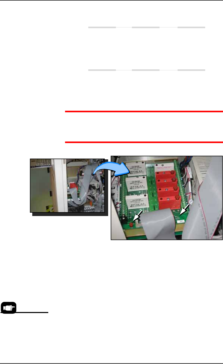
Exit the AH500 and switch off machine power. Check the fuses
on the Opto PCB, inside the right access panel.
WARNING: Electric shock hazard. The PCB has a spot on the
near, right corner for testing the fuse. The PS Machine power must
be ON for this test. Use extreme caution when the access panel is
open and the power is on.
Figure 4-58: The Opto PCB with spare fuse (left arrow) and fuse tester
labeled 1A2. PS388 shown. The location for PS588 is farther toward
the back.
Air Pressure Problems
There is no main air pressure.
Make sure that the main air switch on the Power Panel is in the
ON position.
Check that the air regulator on the Power Panel displays within
the acceptable range: 5.5 ±0.7 Bar (80 ±10 PSI).
If not, replace the filter: See Replacing the Input Air Filter on page
4-15. The digital display on the regulator will be green when air
Note that there is no air
pressure adjustment for
FlashCORE program-
mers on the PS588.

Maintenance ■ Troubleshooting
4—66 Data I/O • 981-0424-002
back
pressure is within the correct range and red when it is out of
range. The regulator has been set at the factory and is not adjust-
able.
There is no or low vacuum on the PNP Probe.
(Models prior to Feb. 2009) Check that the break-away probe tip
is snapped fully into place .
(Models Feb. 2009 or newer) Check that the probe is not loose
and that the o-ring is not destroyed or leaking. Refer to Checking
the Probe Assembly on page 4-12.
Determine if the PNP head probe is clogged. Clean if necessary.
Check the Probe vacuum and blow-off solenoids as follows:
1. At the Gantry Window, click the Actuator tab.
2. In the Actuate box click the Vac On (green). You should be able to
hear the vacuum at the probe and see the red LED light at the
lower solenoid on the right side of the head.
3. Click Vac Off. The lower LED extinguishes.
4. Click Blow-Off On (green). A red LED should light on a solenoid
to the right of the head and just above the Vac solenoid.
5. Click Blow-Off Off (red).
Tube Input and Output Problems
Neither of the tube platforms vibrates.
Make sure that tube input or tube output has been selected on
the Setup Window.
Make sure the vibration controls are rotated clockwise for more
vibration.
Only one tube platform vibrates.
Check the fuse.
For PS Machines delivered prior to 2009 only—
Switch off the PS Machine and check the 2 A 250 V fuse above
the three-wire connector on the back of the I/O Controller. The
input vibrating motor connector is labeled 9 1; the output vibrat-
ing motor connector is labeled 9 2.???
Check the power cable source connection.???
Check the 5A 250 V fuse on the bottom of the vibration control-
ler box (behind the control knobs).
If the fuses are continually being blown, the vibration controller
box may be defective and must be replaced. You can switch the