PS288_PS388_PS588_981-0424-002D - 第210页
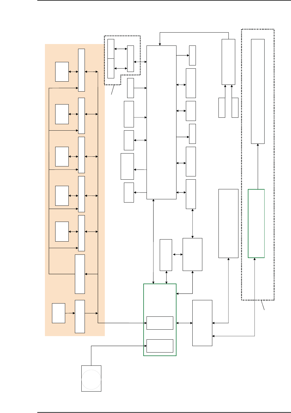
Maintenance ■ Troubleshoot ing 4—70 Data I/O • 981-0424 -002 back Functional Block Diagr am PS SYSTEM FUNCTIONAL BLOCK DIAGRAM HANDLER PC CAMERA DIGITAL IO SOCKET OPENER LIGHT TOWER TRAY FEEDERS TAPE OUT PLC TUBE IO TAPE…

■ Troubleshooting ◘ PS Computer Failure
PS Series Owner’s Manual 4—69
back
9. Turn the PS System on.
10. After it starts up press Control + f to view the FastBuild Utility.
11. Assign RAID 0 (the new drive) to RAID 1. (It should display (2)
RAID 1 drives.)
12. For the fastest rebuild, leave the PS System power on for about
seven hours for the RAID mirror backup system to rebuild the
file system on the new drive. (If it gets turned off, the backup
drive continues to get rebuilt the next time the power is turned
on.)
Note: There will be no obvious on-screen indication that the new
drive is running or being rebuilt.
[Model built prior to 2011] If you have a ghost backup of your
hard drive, follow the instructions of the ghost software to install the
backup. If you have any questions, contact Data I/O Service.
Maintenance ■ Troubleshooting
4—70 Data I/O • 981-0424-002
back
Functional Block Diagram
PS SYSTEM FUNCTIONAL BLOCK DIAGRAM
HANDLER PC
CAMERA
DIGITAL IO
SOCKET
OPENER
LIGHT
TOWER
TRAY
FEEDERS
TAPE OUT PLC
TUBE IO TAPE IN
PNP
VAC/BLOWOFF
TRAY
PRESENT
LASER
MARKING HEAD
SHUTTLE
VAC/BLOWOFF
MAIN AIR
SERVO
CONTACTOR
ETHERNET (MODBUS PROTOCOL)
Z AXIS CONTROLLER AXIS CONTROLLER X AXIS CONTROLLER Y AXIS CONTROLLER
MOTION CONTROL
AMP ENABLE RELAYS
(OPTO 22)
Motor Motor Motor Motor
HOMING RELAYS
(OPTO 22)
SENSORS
USER
INTERFACEE
VISION CARD
MOTION CARD
E-STOP CONTROLLER
DOORS
E-STOP
16 PORT SWITCH
Up to 12 FC Programmers PS588
Up to 4 Programmers PS288, PS388
Up to 12 PCs 104
Up to 12 OPTIMA Programmers
10BaseT
10Base2
PARALLEL
PORT
PS588 ONLY
LASER
COMPUTER
RS232
USB
10BaseT
USB
USB
SHUTTLE CONTROLLER
Motor
V-TEK PNP HEAD
TAPE OUT

■ Tape Output System ◘ Cleaning the Pressure Seal
PS Series Owner’s Manual 4—71
back
Tape Output System
The Tape Output System is an optional system for placing and taping
programmed devices into device tape.
Items not covered here can be found in the TM-50 Taping Module
User’s Guide that came with your PS System.
The Tape Output also uses the Shuttle Transfer System to deliver
devices to it. For maintenance issues regarding the Shuttle System see
The Marking Systems and Shuttle on page 4-34.
Cleaning the Pressure Seal
The Pressure Seal Tape Output System requires cleaning to prevent
problems with breaking the device tape or tearing the tape sprocket
holes. The cleaning process removes adhesive built up from the cover
tape application rollers and the drive sprocket top pressure idler
wheel.
The Tape Output System also employs a PNP head. For information
on cleaning and maintaining the Probe tip see PNP Probe on page 4-12.
Cleaning Tools Required:
• Dry or damp shop towel
• A reel of empty device tape (carrier tape)
• A reel of cover tape
To clean the Pressure Seal Tape Output System:
1. Preparation—
1a. Switch on the PS System power and air.
2. Start a job—
2a. Start TaskLink. (Optional and deprecated: start AH500 by dou-
ble-clicking the AH500 icon on the Windows Desktop, and then
skip Step 2c below.)
2b. Select a job that requires the use of the tape output.
2c. Click Run (and Yes or Ok to subsequent dialogs), which opens
AH500 automatically.
2d. Click Start.
2e. Switch on the Tape Output Controller by pushing the red Power
button. Refer to Figure 4-61.
3. Configure the Tape Output Controller—
3a. At the V-TEK start-up screen, select Setup by pressing the left
arrow button.