PS288_PS388_PS588_981-0424-002D - 第214页
Maintenance ■ Tape Output System 4—74 Data I/O • 981-0424 -002 back 7a. Gently remove the tw o O-rings from the drive sprocket idler . 7b. Using a shop cloth and alcohol or a commercial alcohol wipe, remove all adhesiv e…
■ Tape Output System ◘ Cleaning the Pressure Seal
PS Series Owner’s Manual 4—73
back
At the Jog menu
• jog the device tape forward to align the pocket with the
PNP head.
At the Mode menu
• select PSA mode for pressure seal cover tape. An asterisk indi-
cates the current setting. Then press ESC.
Note: The Heat Seal switch should be OFF.
At the Run menu
•select Run Mode. The run window displays all the selected setup
parameters.
• verify all settings for accuracy.
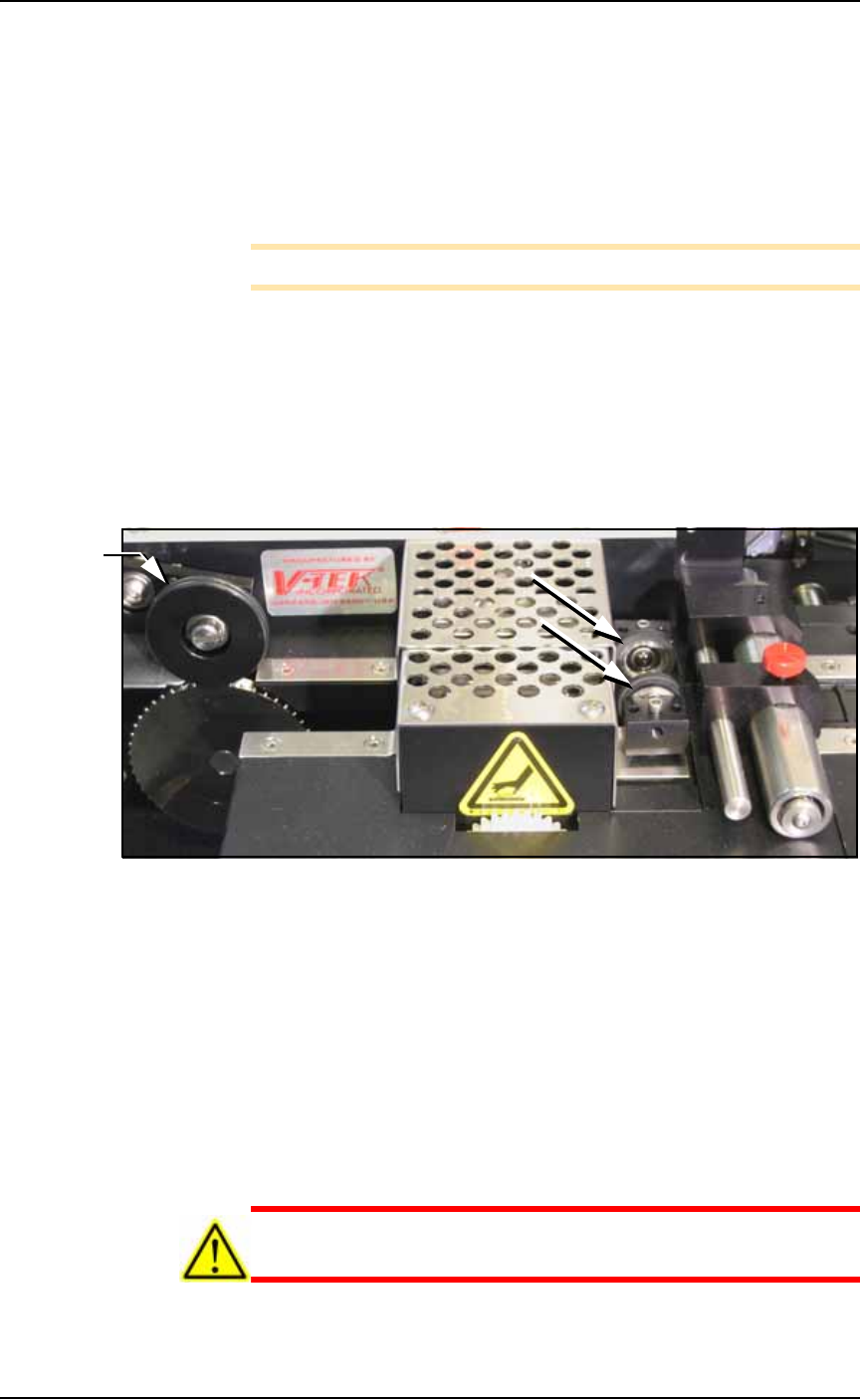
4. Inspect the PSA Seal Rollers (cover tape rollers)—
4a. Inspect the seal rollers for build up of adhesive from the cover
tape. See Figure 4-62.
Figure 4-62: On the Tape Out Module, the PSA Seal Rollers (arrows)
and Sprocket Idler with O-rings.
5. If adhesive buildup exists on the PSA Seal rollers—
5a. Using a shop towel and alcohol or alcohol wipes, clean the adhe-
sive build up from the cover tape application rollers. Hold the
alcohol cloth on the roller and rotate the roller 360°.
5b. Repeat procedure for the other application roller.
6. Inspect drive sprocket idler and rubber O-rings—
6a. Inspect the drive sprocket top idler and rubber O-rings for any
build up of adhesive from the cover tape. See Figure 4-62.
7. If adhesive buildup exists on the idler and O-rings—
CAUTION: O-rings might be easily damaged. Handle gently to
avoid breaking them.
O-rings

Maintenance ■ Tape Output System
4—74 Data I/O • 981-0424-002
back
7a. Gently remove the two O-rings from the drive sprocket idler.
7b. Using a shop cloth and alcohol or a commercial alcohol wipe,
remove all adhesive from O-rings.
7c. Wipe the idler clean.
7d. Reinstall the dry O-rings onto the idler.
Adjusting Pressure of the PSA Seal
Rollers
1. Advance the device tape with the cover tape through the Seal
Rollers using the manual advance pedal. Advance enough pock-
ets to correctly align the cover tape on the carrier tape.
2. Perform a peel back test by peeling the cover tape from the carrier
tape. Notice how well the cover tape adheres to the device tape.
Perform a twist test by giving the tape a slight twist. Notice if the
cover tape detaches from the device tape.
If either test produces loose cover tape, increase the application
roller pressure by screwing the PSA Seal pressure adjustment
screw in (clockwise).
If both tests look acceptable, visually inspect the sealed device
tape for adhesive that may have been squeezed out during
application. If adhesive is visible, the Seal Roller pressure is too
high. Decrease the application roller pressure by screwing the
PSA Seal pressure adjustment screw out and retest.
Troubleshooting the Tape Output
System
The Tape Output System contains sensors that detect these fault con-
ditions:
• a device is on top the device tape (carrier tape)—Track Jam Sen-
sor
• no cover tape is on the reel—Cover Tape Sensor
• device tape is not properly inserted in the device tape
track—Device Tape Present Sensor
• a pocket in the carrier tape is empty—Pocket Empty Sensor
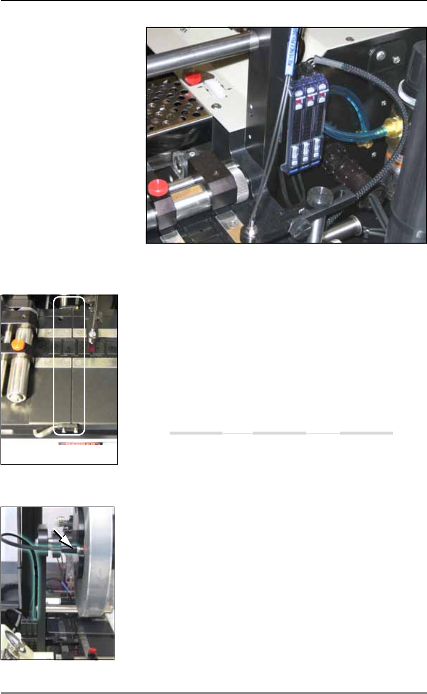
When the AH500 software displays the error message Tape Out Unit,
one of the tape output system sensors has been triggered. The most
likely sensors to trigger are the Device Jam and Device Tape sensors.
See Figure 4-63.
■ Tape Output System ◘ Troubleshooting the Tape Output System
PS Series Owner’s Manual 4—75
back
Figure 4-63: Optical Fiber Amplifiers: (left to right) Cover Tape Present,
Empty Pocket, and Device Tape Present.
Track Jam Sensor and Controller
The Track Jam sensor detects when a device is not properly seated in
the pocket. This sensor is located on the Adjustable Loading Track
immediately before the carrier tape enters the cover taping area.
Tape Out Unit error message displays and a red LED lights in the
Device Jam Sensor.
Use a vacuum tool to seat the device in the device tape pocket.
Re-seat the device tape in the Adjustable Loading Track.
Use air to blow any debris out of the Device Jam sensor path.
Adjust the Device Jam Sensor Controller. See below.
Cover Tape Sensor and Amplifier
The Cover Tape sensor detects when there is no cover tape on the
reel. When the Cover Tape sensor is triggered, a red LED is illumi-
nated in the Cover Tape Sensor Controller.
Error message Tape Out Unit displays and a red LED is illumi-
nated in the Cover Tape Sensor amplifier (left amplifier).
Replace the empty cover tape reel with a full one.
If the reel still contains cover tape, adjust the Cover Tape Sensor
Controller. See below.
Adjusting the Cover Tape Sensor Controller
1. Ensure that the Output Selector mode is set to D.ON by pressing
the Mode button. (There may be an L/D ON button or toggle to
change the mode.)
The Track Jam sensor