PS288_PS388_PS588_981-0424-002D - 第216页
Maintenance ■ Tape Output System 4—76 Data I/O • 981-0424 -002 back 2. Install a roll of cover tape onto the spindle. 3. Press and release the SET button in the left amplifier . 4. Remove the cov er tape. 5. Press and re…
■ Tape Output System ◘ Troubleshooting the Tape Output System
PS Series Owner’s Manual 4—75
back
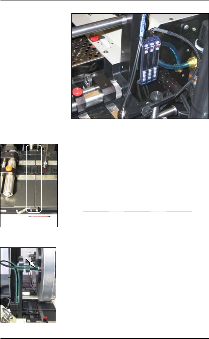
Figure 4-63: Optical Fiber Amplifiers: (left to right) Cover Tape Present,
Empty Pocket, and Device Tape Present.
Track Jam Sensor and Controller
The Track Jam sensor detects when a device is not properly seated in
the pocket. This sensor is located on the Adjustable Loading Track
immediately before the carrier tape enters the cover taping area.
Tape Out Unit error message displays and a red LED lights in the
Device Jam Sensor.
Use a vacuum tool to seat the device in the device tape pocket.
Re-seat the device tape in the Adjustable Loading Track.
Use air to blow any debris out of the Device Jam sensor path.
Adjust the Device Jam Sensor Controller. See below.
Cover Tape Sensor and Amplifier
The Cover Tape sensor detects when there is no cover tape on the
reel. When the Cover Tape sensor is triggered, a red LED is illumi-
nated in the Cover Tape Sensor Controller.
Error message Tape Out Unit displays and a red LED is illumi-
nated in the Cover Tape Sensor amplifier (left amplifier).
Replace the empty cover tape reel with a full one.
If the reel still contains cover tape, adjust the Cover Tape Sensor
Controller. See below.
Adjusting the Cover Tape Sensor Controller
1. Ensure that the Output Selector mode is set to D.ON by pressing
the Mode button. (There may be an L/D ON button or toggle to
change the mode.)
The Track Jam sensor
Maintenance ■ Tape Output System
4—76 Data I/O • 981-0424-002
back
2. Install a roll of cover tape onto the spindle.
3. Press and release the SET button in the left amplifier.
4. Remove the cover tape.
5. Press and release the SET button again.
Note: If an error occurs or the sensor fails to detect the cover tape
after switching from a different type of cover tape, then the Cover
Tape sensor may need to be re-taught to sense that particular type of
cover tape.
Device Tape Present Sensor and Amplifier
The Device Tape Present sensor detects when carrier tape is not
inserted in the track guide. When the Device Tape Present sensor is
triggered, a red LED is illuminated on the Device Tape Sensor ampli-
fier.
A Tape Out Unit error message displays and the red LED on the
Device Tape Sensor amplifier lights (right amplifier).
Replace the device tape reel if it is empty.
Adjust the Device Tape Sensor amplifier if the reel still contains
carrier tape. See below.
Adjusting the Device Tape Sensor Amplifier
1. Ensure that the Output Selector mode on the farthest amplifier is
set to D.ON by pressing the Mode button. (There may be an
L/D ON button or toggle to change the mode.)
2. Set the track width for the target device tape as follows:
2a. pull or push the side nearest the operator to correct width,
2b. Tighten lock knobs.
3. Load a roll of device tape onto the spindle and into the track.
Take up slack in the tape.
4. Press and release the SET button in the right amplifier.
5. Move the cover tape away from the sensor.
6. Press and release the SET button again.
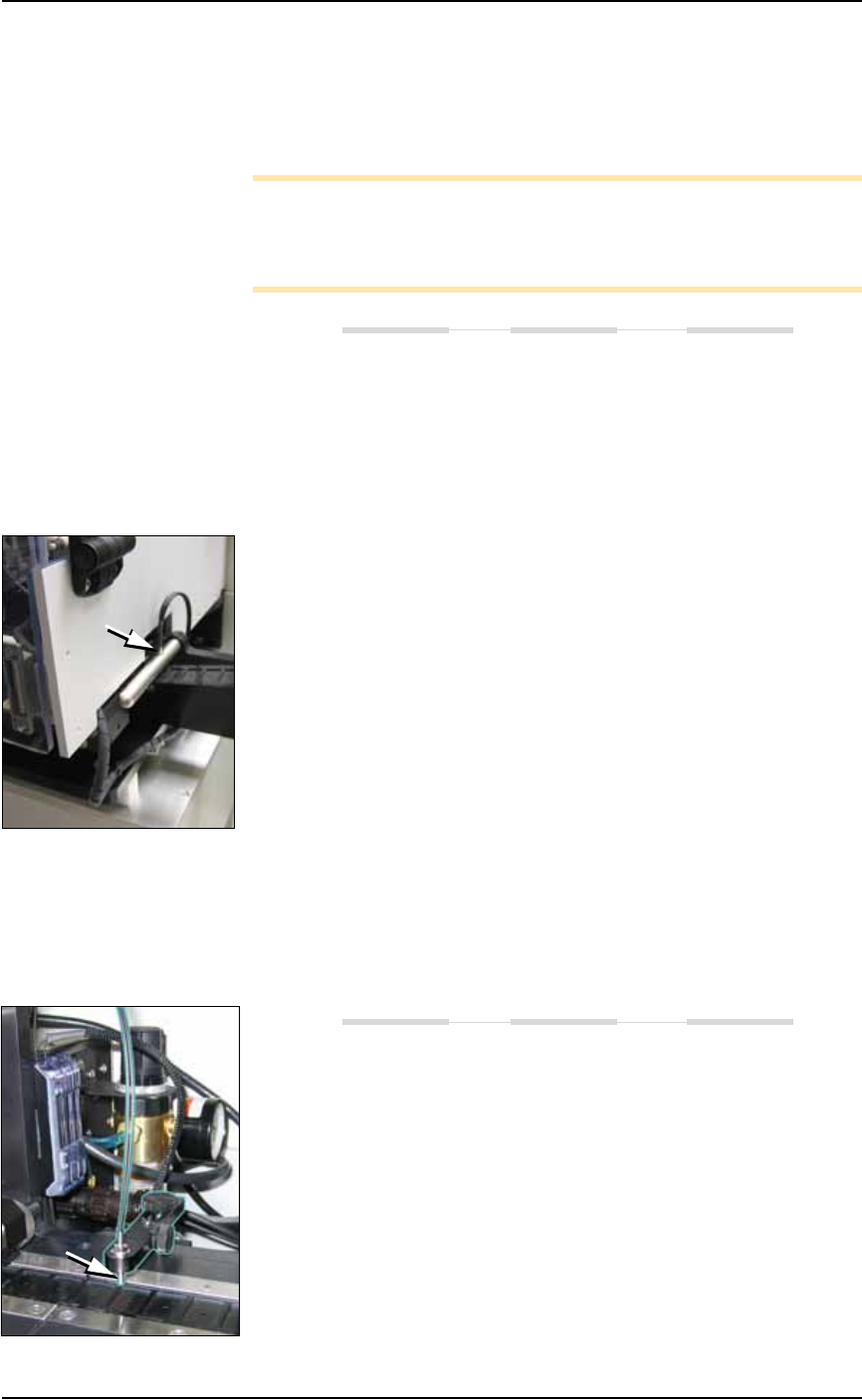
Pocket Empty Sensor and Amplifier
The Pocket Empty sensor alerts the operator when a pocket is empty
as the device tape approaches the cover taping location. This is the
middle sensor in Figure 4-63 on page 4–75.
A Tape Out Unit error message displays and a red LED is illumi-
nated on the Pocket Empty Sensor amplifier.
Adjust the Pocket Empty Sensor as follows:

■ Tape Output System ◘ Troubleshooting the Tape Output System
PS Series Owner’s Manual 4—77
back
1. Set the track width for the target device tape
A) loosen the two Track Width Lock knobs,
B) pull or push the side nearest the operator to correct width,
C) tighten lock knobs.
2. Load a roll of device tape onto the spindle and into the track.
3. Loosen the knob on the left side of the Pocket Empty Sensor
bracket to adjust the height above the tape. Retighten.
4. Loosen the knob on top to center the sensor on the tape.
Retighten.
5. Advance the tape until a pocket with a device in it is centered
under the sensor.
6. Ensure that the Output Selector mode on the middle amplifier is
set to D.ON by pressing the Mode button. (There may be an
L/D ON button or toggle to change the mode.)
7. Press and release the SET button in the right amplifier.
8. Remove the device from the tape pocket.
9. Press and release the SET button again.
Note: This must be reset for each new device type to be taped.