PS288_PS388_PS588_981-0424-002D - 第217页
■ Tape Output System ◘ Troubleshooting the Tape Output System PS Series Owner’s Manual 4—77 back 1. Set the track width for the target device tape A) loosen the two T rack Width Lock knobs, B) pull or push the side neare…
Maintenance ■ Tape Output System
4—76 Data I/O • 981-0424-002
back
2. Install a roll of cover tape onto the spindle.
3. Press and release the SET button in the left amplifier.
4. Remove the cover tape.
5. Press and release the SET button again.
Note: If an error occurs or the sensor fails to detect the cover tape
after switching from a different type of cover tape, then the Cover
Tape sensor may need to be re-taught to sense that particular type of
cover tape.
Device Tape Present Sensor and Amplifier
The Device Tape Present sensor detects when carrier tape is not
inserted in the track guide. When the Device Tape Present sensor is
triggered, a red LED is illuminated on the Device Tape Sensor ampli-
fier.
A Tape Out Unit error message displays and the red LED on the
Device Tape Sensor amplifier lights (right amplifier).
Replace the device tape reel if it is empty.
Adjust the Device Tape Sensor amplifier if the reel still contains
carrier tape. See below.
Adjusting the Device Tape Sensor Amplifier
1. Ensure that the Output Selector mode on the farthest amplifier is
set to D.ON by pressing the Mode button. (There may be an
L/D ON button or toggle to change the mode.)
2. Set the track width for the target device tape as follows:
2a. pull or push the side nearest the operator to correct width,
2b. Tighten lock knobs.
3. Load a roll of device tape onto the spindle and into the track.
Take up slack in the tape.
4. Press and release the SET button in the right amplifier.
5. Move the cover tape away from the sensor.
6. Press and release the SET button again.
Pocket Empty Sensor and Amplifier
The Pocket Empty sensor alerts the operator when a pocket is empty
as the device tape approaches the cover taping location. This is the
middle sensor in Figure 4-63 on page 4–75.
A Tape Out Unit error message displays and a red LED is illumi-
nated on the Pocket Empty Sensor amplifier.
Adjust the Pocket Empty Sensor as follows:

■ Tape Output System ◘ Troubleshooting the Tape Output System
PS Series Owner’s Manual 4—77
back
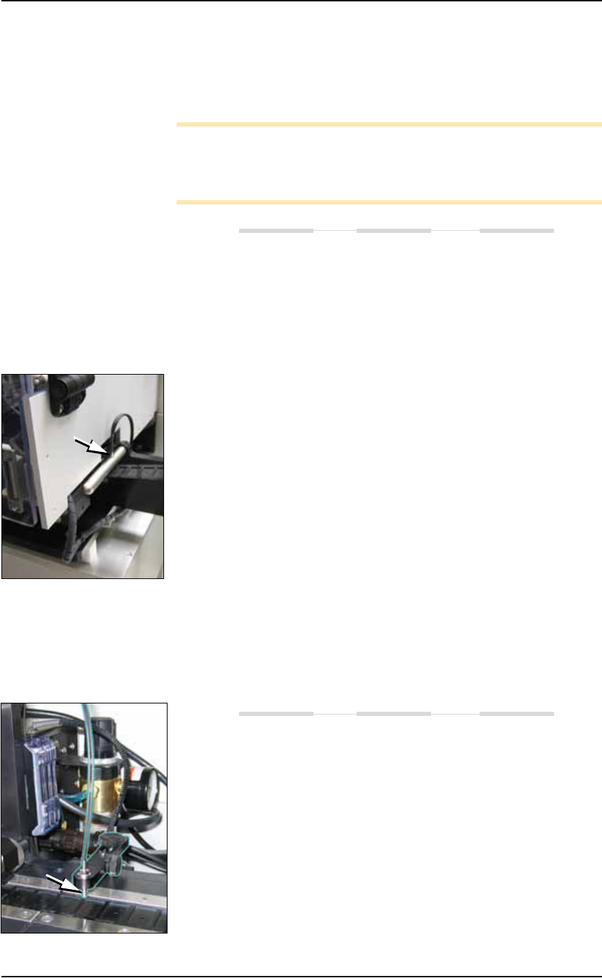
1. Set the track width for the target device tape
A) loosen the two Track Width Lock knobs,
B) pull or push the side nearest the operator to correct width,
C) tighten lock knobs.
2. Load a roll of device tape onto the spindle and into the track.
3. Loosen the knob on the left side of the Pocket Empty Sensor
bracket to adjust the height above the tape. Retighten.
4. Loosen the knob on top to center the sensor on the tape.
Retighten.
5. Advance the tape until a pocket with a device in it is centered
under the sensor.
6. Ensure that the Output Selector mode on the middle amplifier is
set to D.ON by pressing the Mode button. (There may be an
L/D ON button or toggle to change the mode.)
7. Press and release the SET button in the right amplifier.
8. Remove the device from the tape pocket.
9. Press and release the SET button again.
Note: This must be reset for each new device type to be taped.

Maintenance ■ Automatic Tray Feeder
4—78 Data I/O • 981-0424-002
back
Automatic Tray Feeder
The Automatic Tray Feeder is optional equipment to the PS Program-
ming Systems. It is a high-speed tray exchanger, delivering JEDEC
trays to pick and place positions.
Information not found here, but important, can be found in the Tray
Feeder Operation Manual, such as the location of possible pinch points.
Cleaning and Inspecting
If used regularly, the following should be performed monthly:
• Wipe the feeder belts and platform with a cloth dampened with
isopropyl alcohol.
• Check the urethane pinch roller attached to the tray clamping
mechanism for signs of wear or damage. Replace if necessary.
Conveyor Speed Adjustments
The TF20 is designed to keep a tray from stopping too abruptly when
it reaches either end of the conveyor. (Abrupt stops can cause devices
to bounce.) Conveyor speed may need adjustment if trays are stop-
ping too abruptly and devices are moving on the trays.
Two sensors control the speed of the conveyor.
•The Return to Stack sensor is located near the end of the conveyor
closest to the tray stack. The leading edge of a tray moving to the
left passes triggers this sensor.
•The Place in PS Machine sensor is located near the end of the con-
veyor closest to the center of the PS Machine. The leading edge
of a tray moving to the right triggers this sensor.
When either sensor is triggered, the conveyor shifts to slow speed
operation. The speed of the conveyor is adjusted with the potentiom-
eters. Use light force to prevent stripping the potentiometers.
See “Conveyor Ramp Down
Delay” Adjustments in the
separate manual for the
Tray Feeder.