PS288_PS388_PS588_981-0424-002D - 第23页
■ Machine Components ◘ PS288 & PS388 Specificatio ns PS Series Owner’s Manual 1—11 back Machine Components The PS System has many components, or subassemblies, that work together . Refer to the figure below to locate…
Introduction ■ System Description
1—10 Data I/O • 981-0424-002
back
PS288 & PS388 Specifications
Specifications are without optional equipment.
1
Since the monitor arm rotates, length and width dimensions can be
adjusted inversely, up to 13 cm (5 inches). For example, if you sub-
tract 13 cm from length, then add 13 cm to width.
FACILITIES
Air Pressure clean, dry, oil-free air at 621-827
kilopascals (90 to 120 PSI)
Air Flow 85 liters/minute (3 SCFM) constant
AC Input Voltage 208-240 VAC, single phase
AC Input Frequency 50–60 Hz
AC Input Power (max) 10 Amps
PS288/PS388 DIMENSIONS
Length (including monitor)
1
127 cm (50 inches)
Width (including monitor)
1
112 cm (44 inches)
Height + [light tower] 163 cm (64 inches) [56 cm, 22 in.]
Weight 364 kg (800 lbs)
ENVIRONMENT
Operating Temperature +13° to +30° C (+55° to +86° F)
Relative Humidity 35% to 90% non-condensing
■ Machine Components ◘ PS288 & PS388 Specifications
PS Series Owner’s Manual 1—11
back
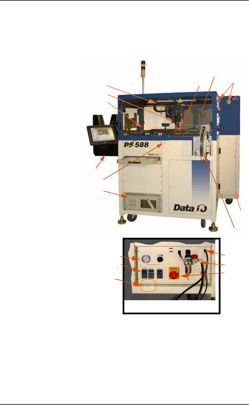
Machine Components
The PS System has many components, or subassemblies, that work
together. Refer to the figure below to locate primary components.
Figure 1-2: Primary components of the PS588. Other PS Systems are
similar. Some optional assemblies are also shown.
1. Light Tower • page 1-12
page 3-25
2. E-Stop page 1-4
3. Gantry • page 1-12
4. PNP head • page 1-12
5. Workspace
6. Option Bay • for Marking
System or Tape Output
7. Tape Input • page 1-17
page 2-16
8. Automatic Tray Feeder
• page 1-16 page 2-10
9. Tape Output • page 1-17
page 2-19
10. ESD Strap Connection
1
• page 1-15
11. Handler Computer • page
1-14
12. Safety Shields page 1-5
13. Programmers • page 1-13
14. Vision System
• page 1-14
15. Power Panel • page 1-17
16. Socket Opener air pres-
sure page 4-8
17. Circuit Breakers • page
1-18
18. Ethernet connection
page 2-4
19. Main air page 2-2
20. Power switch page 2-3
21. Serial Number
•brief description, more detail
1
A ESD Strap connection is on the back,
also. On PS588 it’s on the right corner
post. On other models, it’s in the center.
1
2
3
4
5
6
7
8
9
12
13
14
15
Far side
Back of machine, lower right corner
Programmers (not visible here)
16
18
19
17
20
21
11
10
Introduction ■ Machine Components
1—12 Data I/O • 981-0424-002
back
Component Descriptions
Light Tower
Allows monitoring the status of the PS System from a distance while
the system is processing devices. See Light Tower Interpretation on page
3-25 for a complete description of lamp colors and significance.
Gantry
Travels along X- and Y-axes moving the PNP head to different loca-
tions within the work envelope.
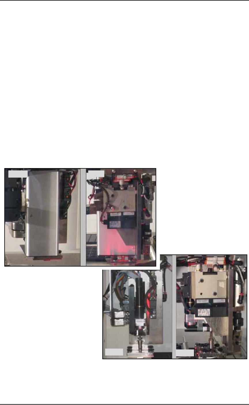
Pick and Place Head (PNP Head)
The PNP head is responsible for moving devices to and from their
respective stages within the workspace. It moves devices in four axes,
X, Y, Z and R.
The PNP head uses different sized probe tips to accommodate the
great number of device types that are available. See Installing the Cor-
rect Probe Tip on page 3-7. During operation, vacuum at the probe
holds a device. A vacuum sensor detects presence of a device or not.
Figure 1-3: PNP heads: The new J-Head (top) and the IntellePro Head
(bottom).
Side
Front
Side
Front