PS288_PS388_PS588_981-0424-002D - 第25页
■ Machine Components ◘ Component Descrip tions PS Series Owner’s Manual 1—13 back The PNP head picks up the device and moves it to the Vision System camera where it compares the device position on the probe to a dig- ita…
Introduction ■ Machine Components
1—12 Data I/O • 981-0424-002
back
Component Descriptions
Light Tower
Allows monitoring the status of the PS System from a distance while
the system is processing devices. See Light Tower Interpretation on page
3-25 for a complete description of lamp colors and significance.
Gantry
Travels along X- and Y-axes moving the PNP head to different loca-
tions within the work envelope.
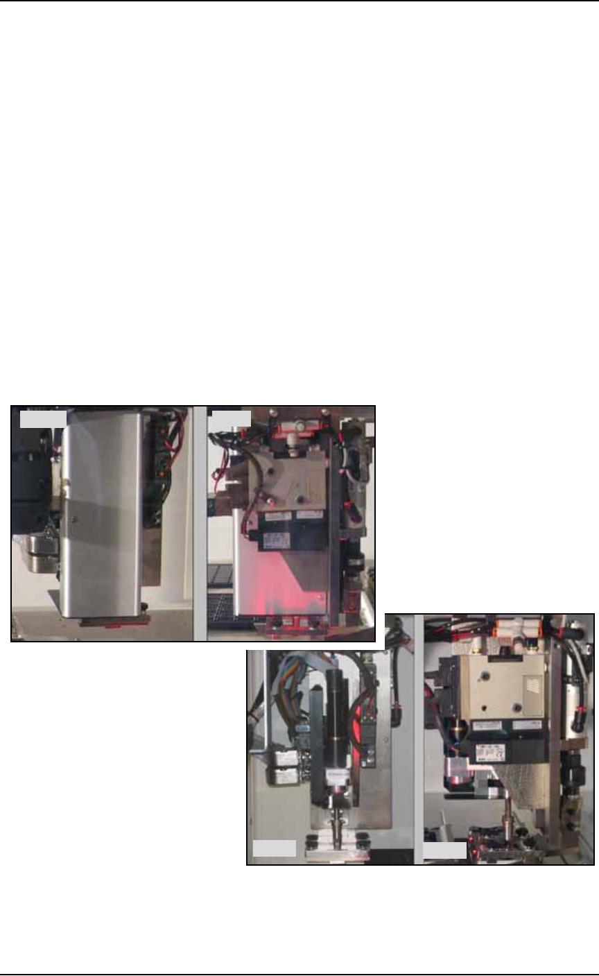
Pick and Place Head (PNP Head)
The PNP head is responsible for moving devices to and from their
respective stages within the workspace. It moves devices in four axes,
X, Y, Z and R.
The PNP head uses different sized probe tips to accommodate the
great number of device types that are available. See Installing the Cor-
rect Probe Tip on page 3-7. During operation, vacuum at the probe
holds a device. A vacuum sensor detects presence of a device or not.
Figure 1-3: PNP heads: The new J-Head (top) and the IntellePro Head
(bottom).
Side
Front
Side
Front
■ Machine Components ◘ Component Descriptions
PS Series Owner’s Manual 1—13
back
The PNP head picks up the device and moves it to the Vision System
camera where it compares the device position on the probe to a dig-
ital image. It corrects for misalignments before the device is placed
into the programming socket. To place a device at a target location,
the probe lowers, vacuum is turned off and blow-off air is momen-
tarily turned on.
The PNP head carries the Socket Opener. The exception to this is the
PS588 with FlashCORE Programmers (no Optima Program-
mers)—actuators on the programmers open sockets versus openers.
WARNING: Collision hazard. The gantry system and associated
components move with great speed and force, and have the
potential to cause great bodily harm. Do not bypass the safety
interlocks or operate the PS Machine with the safety shields open
or removed.
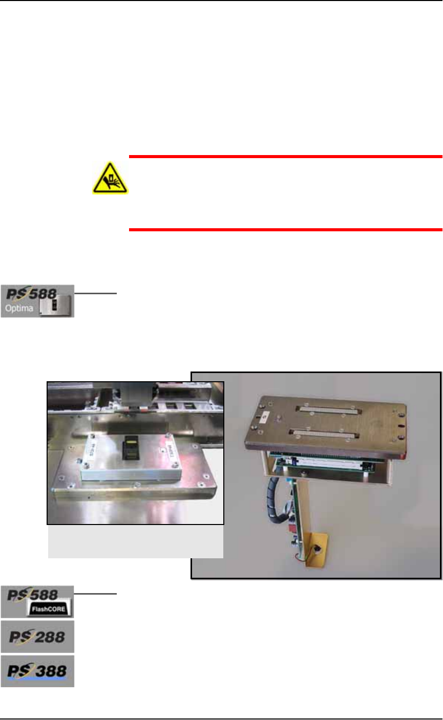
Programmers
Optima Programmers (also called Universal Programmers) are an
earlier design and support the most Flash devices including logic
devices and many microcontrollers. Optima programmers can be
mounted only on PS588, even alongside FlashCORE programmers.
An Optima Support Kit is available for PS588 customers needing to
replace their Optima programmer. PS588 customers without an
Optima programmer who wish to install one should contact Data I/O.
Figure 1-4: An Optima Programmer for PS588 only. This programmer
requires an Optima adapter.
Data I/O’s FlashCORE programming modules are the fastest pro-
grammer architecture available. Modules come in single, dual, or
quad units. PS588 FlashCORE programmers have socket actuation
built in.
An Optima Programmer installed, with
a Socket Adapter on it.
Introduction ■ Machine Components
1—14 Data I/O • 981-0424-002
back
Figure 1-5: A FlashCORE Programmer with a Socket Adapter and
Actuator Plate installed on it.
Vision System
The camera and associated components of the Vision System provide
fine alignment of devices removed from the input media before
inserting them into the programming sockets or marking pedestal.
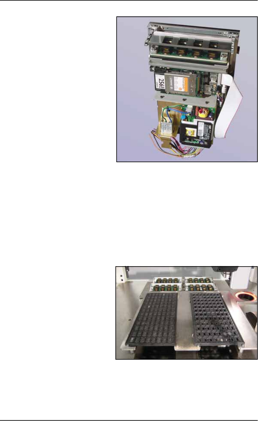
Static Tray Mount
Using positioning pins and magnetic L-shaped brackets (or thumb
screws on some models), JEDEC and non-JEDEC standard trays are
held firm for the PNP head to pick devices and return them after pro-
cessing.
Figure 1-6: Static tray mount on PS288.
Handler Computer
The computer that hosts TaskLink software and the AH500 software,
monitors all sensors. It also hosts the Vision System and in some