PS288_PS388_PS588_981-0424-002D - 第28页
Introduct ion ■ Machine Components 1—16 Data I/O • 981-0424-002 back Figure 1-7 : Paper Labeler . (Y our labeler may look dif ferent.) Laser Marking The Laser Marking System uses a CO 2 laser to mark parts. The laser app…
■ Machine Components ◘ Component Descriptions
PS Series Owner’s Manual 1—15
back
models hosts the Laser Software if applicable. The computer contains
a CPU that runs Microsoft Windows XP Operating System (at time of
release).
CAUTION: Possible machine damage. The PS System should
never have software added unless instructed to do so by Data I/O
Customer Support. Adding software to the PS System can cause
damage and/or cause the system to operate improperly. Adding
software without specific instruction from Data I/O Customer Sup-
port will void the warranty and may incur service charges.
Keyboard and Track Pad
Used for operation. Can be used instead of the touch screen monitor.
ESD Strap Connection
When operators plug an antistatic wrist strap into the ESD strap con-
nection, it reduces the risk of damage to devices and Socket Adapters
from electrostatic discharge (ESD).
Touch Screen Monitor
The display screen (user interface) on the PS System, accepts input
when touched or tapped with a finger. The touch screen may be used
instead of the keyboard and track pad.
Note: Throughout this Owner’s Manual, the term click is also
used to mean tap when using the touch screen monitor.
Safety Shields
Designed to protect against injury and damage from the PNP head
movement, the safety shields are an important safety feature, stop-
ping the gantry when they are opened. For more information see
Safety Shields with Interlocks on page 1-5.
(Optional) Marking System
A Label Marking or Laser Marking System is used to mark devices
for identifying at a later time. Either marking system is installed in
the Option Bay at the back of the PS System.
The marking systems use the Shuttle Transfer Assembly to move
devices to and from the marking stage. The shuttle transfer is a
belt-driven shuttle system that has two pedestals for holding devices.
If the Tape Output System is selected in addition to a marking
system, then only one of the pedestals is used since both marking and
the tape output systems are in the Option Bay.
Label Marking
The Label Printing System only uses one pedestal.
Introduction ■ Machine Components
1—16 Data I/O • 981-0424-002
back
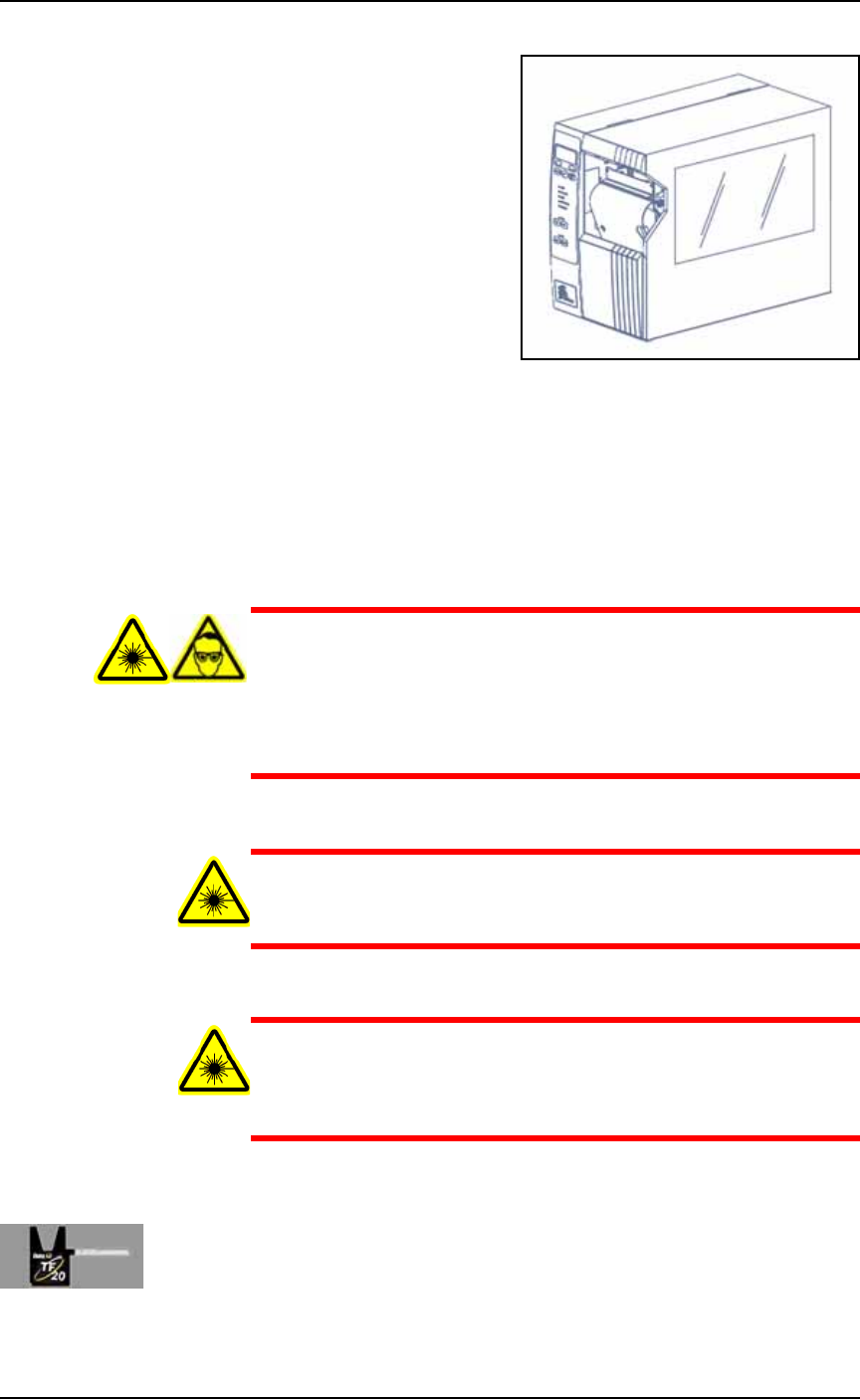
Figure 1-7: Paper Labeler. (Your labeler may look different.)
Laser Marking
The Laser Marking System uses a CO
2
laser to mark parts. The laser
applies a user-defined mark. The laser marking system operates as a
Class 1 laser system (CDRH classification), and therefore uses inte-
grated interlocks to prevent the laser from firing while any cover is
open. The laser should never be operated without safety covers in
place.
WARNING: Blindness hazard! When servicing, always wear eye
protection when the laser access doors are open. Direct or diffuse
laser radiation can damage eyes. Goggles must block 10.57 to
10.63
μ
m laser radiation. Goggles protect against scattered
energy but not against direct viewing of the laser beam or reflec-
tions from metallic surfaces.
WARNING: Serious burn hazard! Laser radiation, whether direct
or diffuse, can cause serious burns. When servicing, keep hands
and other parts of the body out of the path of the laser beam.
WARNING: Toxic fume hazard! Laser marking generates vapors,
fumes, and particles that may be noxious, toxic, or even fatal. Fol-
low maintenance procedures on the fume extractor. Use proper
ventilation.
For additional safety information, see Laser Safety on page 1-24.
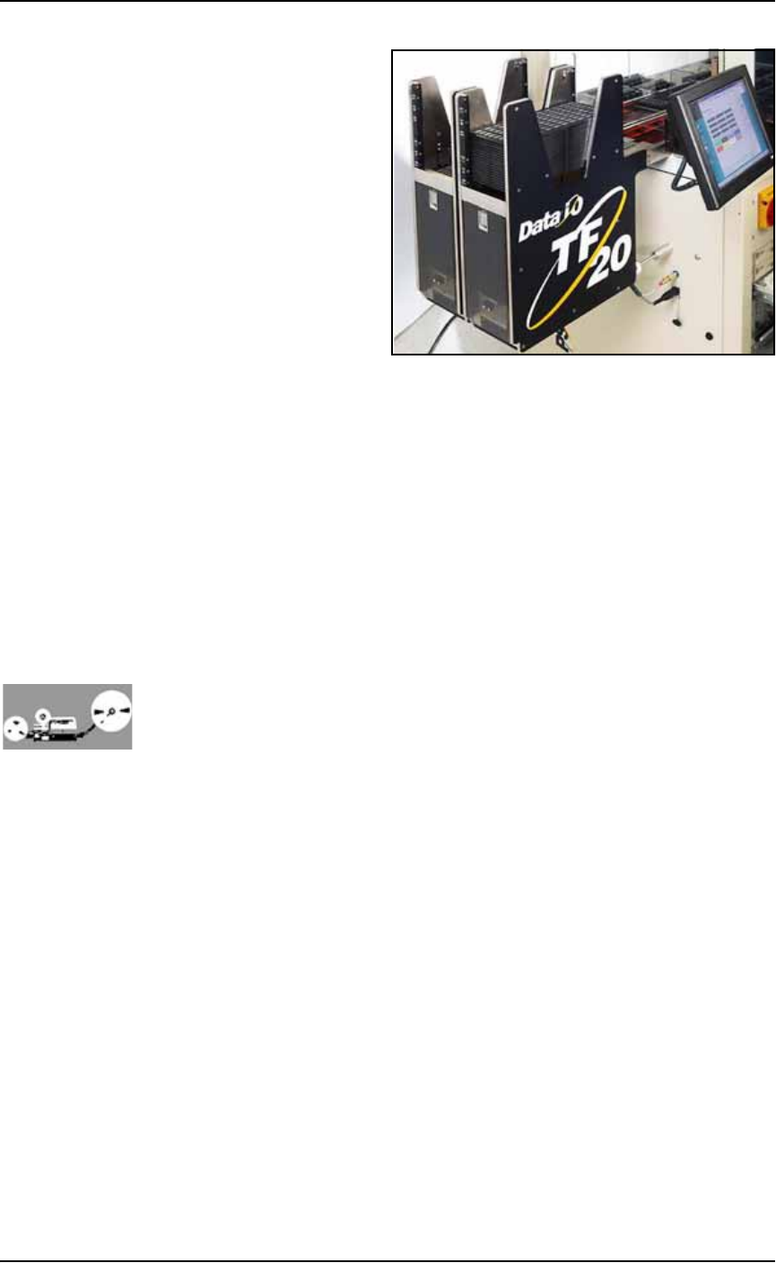
(Optional) Automatic Tray Feeder
Designed to automatically supply devices in trays to the PS System,
the TF20 Automatic Tray Feeder accepts thin or thick JEDEC trays.
■ Machine Components ◘ Component Descriptions
PS Series Owner’s Manual 1—17
back
Figure 1-8: TF20 Tray Feeder.
(Optional) Tube Input and Output Modules
The input tube holds blank devices and the output tube collects
devices after programming. Vibration mechanisms keep devices
sliding freely by gently vibrating the tubes to reduce the likelihood of
device jams. Vibration adjustment controls are located on the front of
the PS System.
(Optional) Tape Input Module
The tape input module is a chip feeder which provides devices for
programming. Each device is picked from a carrier tape pocket and
placed into a programming socket.
(Optional) Tape Output Module
The tape output module, mounted on the Option Bay, uses a reel of
empty carrier tape to hold devices after they are programmed. Pro-
grammed devices are placed into empty pockets on the carrier tape.
The carrier tape advances through either a heat seal or pressure seal
unit that applies cover tape to the carrier tape.
Power Panel
The Power Panel is on the back of the machine at the lower, right
corner.
Connections
The Power Panel allows for the attachment of AC power and air.
Optionally, you can connect an ethernet cable for internet connection.
Controls
Mounted on the Power Panel are the main power switch and the
main air regulator and filter. There is a second regulator with a sepa-
rate gauge for adjusting socket opener pressure. See Adjusting the
Socket Actuator Air Pressure on page 4-8.