PS288_PS388_PS588_981-0424-002D - 第30页
Introduct ion ■ Machine Components 1—18 Data I/O • 981-0424-002 back Figure 1-9: P ower Panel on the back of th e PS Machin e. Circuit Breakers There are three circuit breakers on the P ower P anel. Programmers 230 V 10 …
■ Machine Components ◘ Component Descriptions
PS Series Owner’s Manual 1—17
back
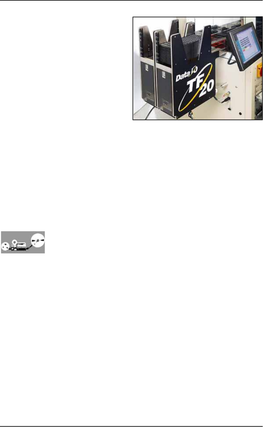
Figure 1-8: TF20 Tray Feeder.
(Optional) Tube Input and Output Modules
The input tube holds blank devices and the output tube collects
devices after programming. Vibration mechanisms keep devices
sliding freely by gently vibrating the tubes to reduce the likelihood of
device jams. Vibration adjustment controls are located on the front of
the PS System.
(Optional) Tape Input Module
The tape input module is a chip feeder which provides devices for
programming. Each device is picked from a carrier tape pocket and
placed into a programming socket.
(Optional) Tape Output Module
The tape output module, mounted on the Option Bay, uses a reel of
empty carrier tape to hold devices after they are programmed. Pro-
grammed devices are placed into empty pockets on the carrier tape.
The carrier tape advances through either a heat seal or pressure seal
unit that applies cover tape to the carrier tape.
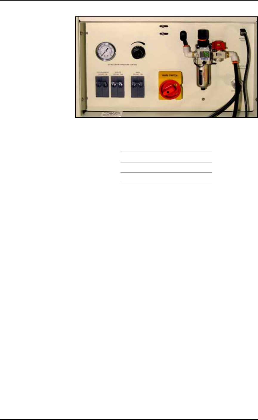
Power Panel
The Power Panel is on the back of the machine at the lower, right
corner.
Connections
The Power Panel allows for the attachment of AC power and air.
Optionally, you can connect an ethernet cable for internet connection.
Controls
Mounted on the Power Panel are the main power switch and the
main air regulator and filter. There is a second regulator with a sepa-
rate gauge for adjusting socket opener pressure. See Adjusting the
Socket Actuator Air Pressure on page 4-8.
Introduction ■ Machine Components
1—18 Data I/O • 981-0424-002
back
Figure 1-9: Power Panel on the back of the PS Machine.
Circuit Breakers
There are three circuit breakers on the Power Panel.
Programmers 230 V 10 A
Servos 230 V 10 A
Main 230 V 15 A
■ Software ◘ Customer-Supplied Software
PS Series Owner’s Manual 1—19
back
Software
Software resides in the Handler Computer. The primary logon for the
Handler Computer is Microsoft Client. The current operating system
(at time of this publication) is Windows XP.
CAUTION: Possible machine damage. Adding software to the
PS System can cause damage and/or cause the system to operate
improperly. Adding software without specific instruction from
Data I/O Customer Support will void the warranty and may incur
service charges.
CAUTION: Possible machine damage. Microsoft Windows system
parameters and network parameters should not be changed
unless instructed to do so by Data I/O Customer Support. Chang-
ing parameters can cause failure and/or damage to systems or
cause improper programming.
Customer-Supplied Software
The PS System should never have other software added without con-
sulting with Data I/O Customer Support.
Antivirus Software
Customer-supplied antivirus software can be installed on the Han-
dler Computer.
CAUTION: Check with Data I/O Customer Support to ensure that
your software is compatible with the PS System, otherwise the
warranty may be voided. Ensure that the antivirus software does
not scan during a job run.
Statistical Process Control Software
Customer-supplied Statistical Process Control software can be
installed on the Handler Computer. See Statistical Process Control Soft-
ware on page 3-55 for more information.
TaskLink
TaskLink
™
for Windows
®
is Data I/O’s versatile application for cre-
ating jobs to run on the PS System. TaskLink resides on the Handler
Computer.