PS288_PS388_PS588_981-0424-002D - 第44页
Setup ■ Connecting Facilities 2—2 Data I/O • 981-0424 -002 back Connecting Facilities The PS System requires two extern al services: pressurized air and electrical power . It also allows on e optional connection to an In…
PS Series Owner’s Manual 2—1
Chapter
2
2Setup
This chapter covers setting up the PS machine as well as set-
ting up equipment on the machine. This includes optional
equipment such as the Option Bay and Tape Output equip-
ment, as well as the various device media choices for running
jobs, such as setting up Static Trays or an Automatic Tray
Feeder.
Installation of the PS Machine is performed by Data I/O service per-
sonnel or an authorized distributor. After the PS Machine arrives,
ensure that there is no damage to the exterior of the crate. Remove the
PS machine from the crate and inspect for damage that may have
occurred during shipping. If no damage is evident, unbolt the
PS machine from the shipping pallet.
The intended area for PS installation must:
• allow at least one meter (36 inches) of clearance on all sides of
the PS machine for opening access panels as well as repairing
and replacing subassemblies,
• provide a solid foundation (for example, a concrete floor). The
PS machine contains a fast-moving gantry with much mass. The
area for it must be stable, solid, and mostly level prior to installa-
tion. If this is not achievable, consider installing the system at
another location.
When at the desired location, adjust the feet to level the PS Machine.
WARNING: Possible machine damage or personal injury. Instabil-
ity such as vibrating, walking, or rocking, may occur if fewer than
four of the installed feet make suitable contact with the floor, or if
the leg locknuts are not tightened against the frame.
Only the adjustable feet provided on the PS machine should be
used for leveling. Do not use shims to assist in leveling.
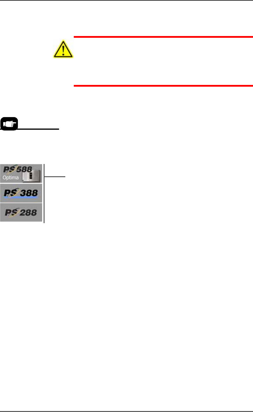
The information in this
Manual applies to the
PS288, PS388 and
the PS588, (referred
to as PS System)
unless otherwise noted.
Setup ■ Connecting Facilities
2—2 Data I/O • 981-0424-002
back
Connecting Facilities
The PS System requires two external services: pressurized air and
electrical power. It also allows one optional connection to an Internet
via a Network connection. These services connect to the PS System at
the Power Panel located on the back of the machine. With the two
required services, the PS System creates all the unique electrical volt-
ages needed as well regulating pneumatic pressure for all systems
within the machine.
Connecting Air
The PS System requires clean, dry, oil-free air from an industrial
grade compressor. The compressor’s tank should be of sufficient size
to maintain constant air pressure at 85 liters per minute (3 Standard
Cubic Feet per Minute).
Note: If the compressor cannot maintain the correct air pressure,
system performance will be affected.
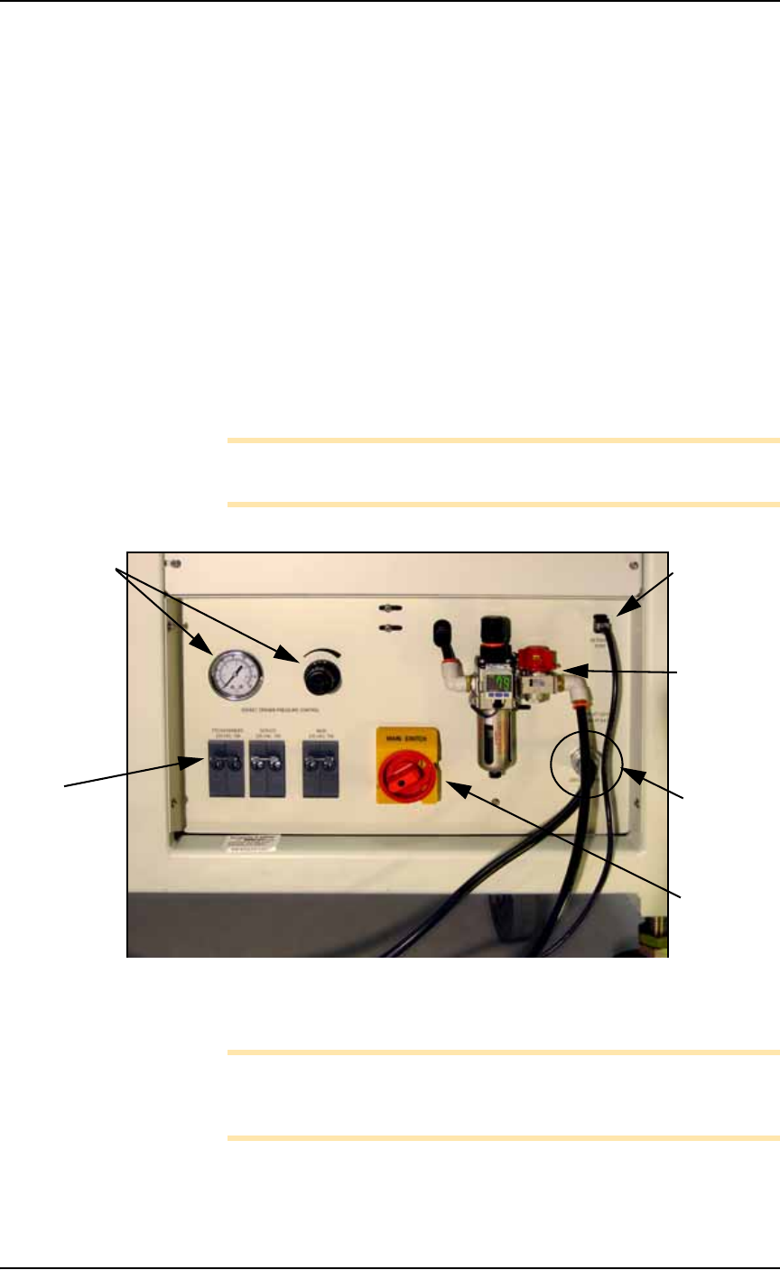
Figure 2-1: The Power Panel on the back of the machine.
Connect the air to the PS System at the main regulator and filter.
Note: The PS System air filter is a secondary filter only. Install a
main 10 micron filter/regulator between the factory compressor and
the PS System.
The external air line should be at least 3 meters (10 feet) long to allow
the supplied air to cool sufficiently so that water vapor contained in
8P8C Ether-
net connec-
tion
Air connec-
tion: main
regulator
and filter
Power cable
(doesn’t discon-
nect here)
Power
Switch
Socket Actua-
tion pressure
regulator &
gauge [PS288
& PS388 and
Optima only
on PS588]
Circuit
Breakers:
See Circuit
Breakers on
page 1-18 for
more informa-
tion.
■ Connecting Facilities ◘ Connecting Electrical Power
PS Series Owner’s Manual 2—3
back
the air condenses and can be extracted. See Figure 2-1 for the location
of the external air line connection.
CAUTION: Possible air system damage. Oil, excessive moisture, or
poorly filtered air will obstruct the system’s internal air pathways,
affect performance, and void the warranty related to air system
failure. If oil or excessive moisture is detected, contact Data I/O
Customer Support or a local Data I/O approved service represen-
tative.
Main Air Pressure Gauge
The main pressure regulator is set at 5.5 ±0.7 Bar (80 ±10 PSI) as
shown on the regulator. This is set in the factory and cannot be
changed.
When air pressure is within range, the regulator readout is green. If
air pressure is above or below the acceptable range, the readout dis-
plays red. If it is red (out of range), contact Data I/O Support or a
qualified service technician.
Socket Opener Pressure
[PS288, PS388, Optima only on PS588] This regulator controls the air
pressure which lowers the Socket Opener that opens sockets. Set the
pressure now using instructions found at Adjusting the Socket Actuator
Air Pressure on page 4-8.
Connecting Electrical Power
Required power is provided through a supplied 3-wire power cable
with one end terminated in an electrical plug as required by the cus-
tomer’s facility. For power specifications, see PS588 Specifications on
page 1-9 or PS288 & PS388 Specifications on page 1-10.
If there is low air pressure
the monitor may display a
message reading No air.