PS288_PS388_PS588_981-0424-002D - 第46页
Setup ■ Connecting Facilities 2—4 Data I/O • 981-0424 -002 back . Figure 2-2: Electrical power cabl e and plug. The machine e nd of the cable is not remo vable. (Optional) Connecting to a Network A Network conne ction is…
■ Connecting Facilities ◘ Connecting Electrical Power
PS Series Owner’s Manual 2—3
back
the air condenses and can be extracted. See Figure 2-1 for the location
of the external air line connection.
CAUTION: Possible air system damage. Oil, excessive moisture, or
poorly filtered air will obstruct the system’s internal air pathways,
affect performance, and void the warranty related to air system
failure. If oil or excessive moisture is detected, contact Data I/O
Customer Support or a local Data I/O approved service represen-
tative.
Main Air Pressure Gauge
The main pressure regulator is set at 5.5 ±0.7 Bar (80 ±10 PSI) as
shown on the regulator. This is set in the factory and cannot be
changed.
When air pressure is within range, the regulator readout is green. If
air pressure is above or below the acceptable range, the readout dis-
plays red. If it is red (out of range), contact Data I/O Support or a
qualified service technician.
Socket Opener Pressure
[PS288, PS388, Optima only on PS588] This regulator controls the air
pressure which lowers the Socket Opener that opens sockets. Set the
pressure now using instructions found at Adjusting the Socket Actuator
Air Pressure on page 4-8.
Connecting Electrical Power
Required power is provided through a supplied 3-wire power cable
with one end terminated in an electrical plug as required by the cus-
tomer’s facility. For power specifications, see PS588 Specifications on
page 1-9 or PS288 & PS388 Specifications on page 1-10.
If there is low air pressure
the monitor may display a
message reading No air.
Setup ■ Connecting Facilities
2—4 Data I/O • 981-0424-002
back
.
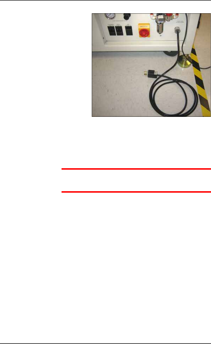
Figure 2-2: Electrical power cable and plug. The machine end of the
cable is not removable.
(Optional) Connecting to a Network
A Network connection is on the Power Panel.
CAUTION: Possible virus hazard. The PS System has no antivirus
software installed from the factory. Prior to connecting to a net-
work, Data I/O recommends installing antivirus software.
To connect to a network, plug in an ethernet cable. Refer to Figure 2-1
on page 2–2. See the next heading, Applying Power, prior to setting up
a network connection.
After starting up and logging on, at the monitor, click My Computer >
Tools > Map Network Drive.
IP Address and Port Number
If you need the IP Address for communicating with other Data I/O
software, they are available via TaskLink. The Port numbers are also
displayed. (Port numbers are the same for all programmers on a
PS Machine.)
Addresses and Port numbers can be found as follows.
1. Start TaskLink on the target PS System. (Closing AH500 will
return to TaskLink.)
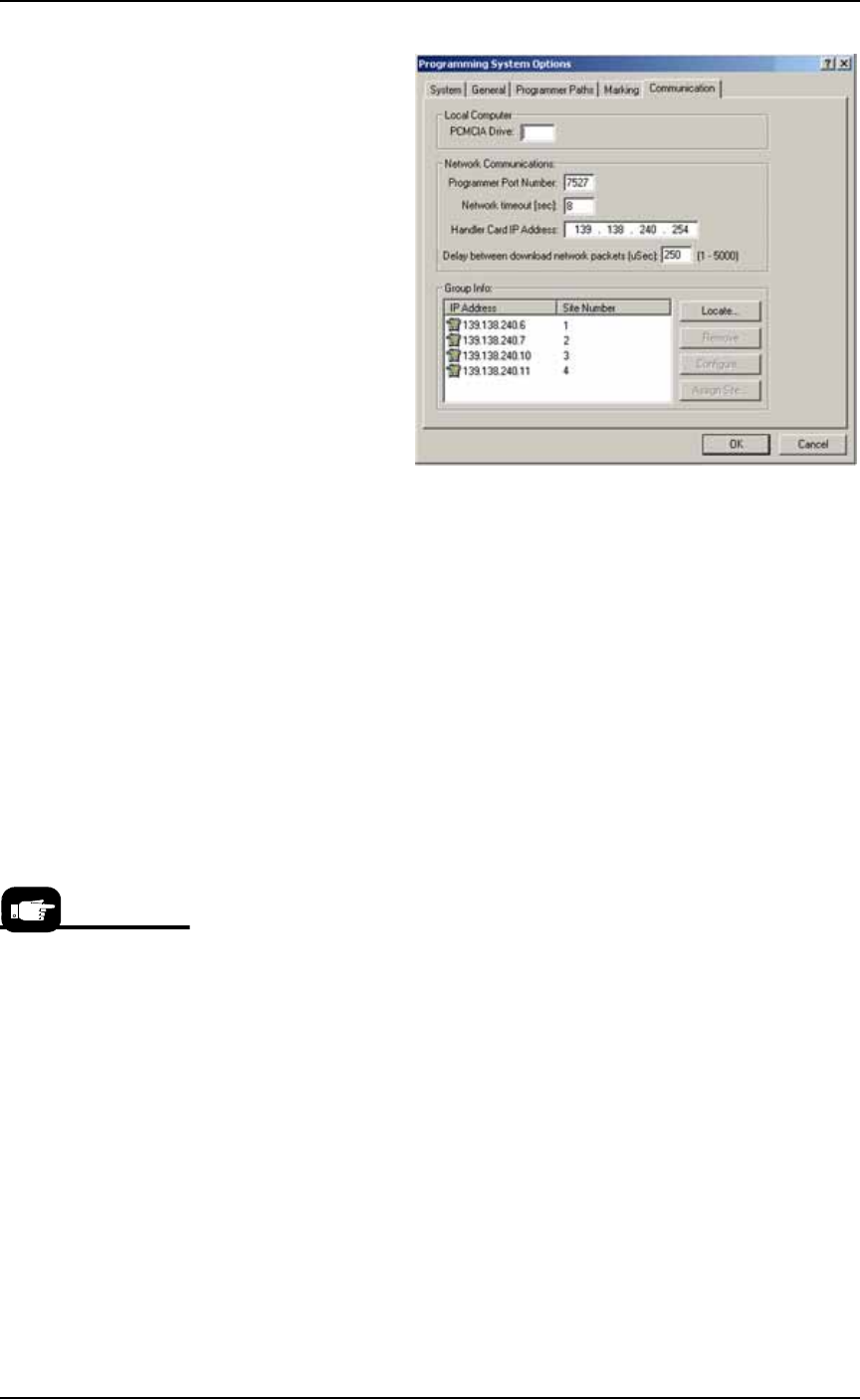
2. Click System > Options, and then the Communication tab. The IP
Address and site numbers are listed in the lower left corner.
■ Applying Power for the First Time ◘ (Optional) Connecting to a Network
PS Series Owner’s Manual 2—5
back
Figure 2-3: TaskLink Communication Tab displays IP Addresses and
site numbers.
Applying Power for the First Time
Before the PS System is turned on for the first time, ensure the fol-
lowing:
The external air line is connected, and the main air valve is open.
All E-Stop buttons are in the released (operating) positions (refer
to Emergency Stop (E-Stop) Buttons on page 1-4 for location).
All safety shields and access panels are closed.
The circuit breakers on the Power Panel on the back of the
PS System are in the ON (UP) position.
The power switch on the Handler Computer is set to the ON
position.
[PS588 Only] (Optional) If you want to change the type of pro-
grammers, see Removing a Programmer on page 4-30.
(Optional) The Socket Adapters required for the job have been
installed on all necessary programmer sites. See Installing Socket
Adapters – FlashCORE on page 3-3 for more information.
[PS588 only] See Installing Socket Adapters – OPTIMA on page 3-6
for more information.
When satisfied, rotate the main power switch on the Power Panel (at
the back of the PS Machine) to the ON position (clockwise).
After power is applied, verify that no obvious failures or electrical
anomalies occur. Verify that the Handler Computer starts properly
and displays a network log-on dialog.
Normal operating pro-
cedure never requires the
Handler Computer
power switch to be
turned off manually.