PS288_PS388_PS588_981-0424-002D - 第50页
Setup ■ Setting Up Input and Output Media 2—8 Data I/O • 981-0424 -002 back Figure 2-5: T o remov e a tray , unscrew the thumb screw and lift the tray out. A second method is NOT RECO MMENDED: pul ling the thumb screw ba…
■ Setting Up Input and Output Media ◘ Setting Up Static Tray Input and Output
PS Series Owner’s Manual 2—7
back
ware, such as Job file, WinAH400.ini file, and printer file. These
input/output media are described in this section:
•Static Tray (below)
• Automatic Tray Feeder
• Tube Input/Output (vibratory)
• Tape Feeder Input
• Tape Output
Setting Up Static Tray Input and Output
The standard configuration for the PS System is static tray input and
static tray output media. The latest tray mounting configuration uses
a spring-loaded thumb screw for holding the tray in place, while the
earlier configuration uses magnetic angle brackets.
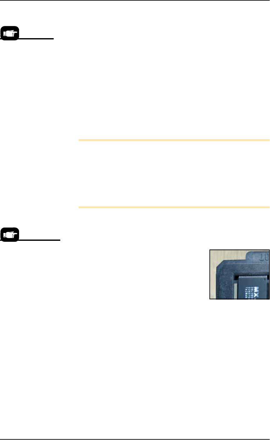
Note: Ensure that blank devices are loaded into the tray with the
correct pin 1 orientation. If pin 1 orientation doesn’t match pin 1
on the sockets, the correct rotation must be taught in the Package
file.
Pin 1 on Data I/O sockets is almost always toward the far side of
the adapter (the back of the PS Machine). Some BGAs and PLCCs
are marked.
Tray Orientation
IF THE TRAY MOUNT IS ORIENTED with the long side parallel to
the Y-axis:
• The input tray goes on the left. Orient the
trays with the beveled corner to the far
left.
IF THE TRAY MOUNT IS ORIENTED with
the long side parallel to the X-axis:
• The input tray goes nearest to the opera-
tor. Trays can be oriented with the bev-
eled corner on the left or right. However,
with Automatic Tray Feeders it must be to the right.
Static Tray Mount with Thumb Screw
To set up the static Thumb Screw Tray input and output:
1. Preparation—
1a. Ensure the PNP head is parked.
1b. Open the front safety shield.
2. Install the Trays—
2a. Set the tray onto the mounting plate inside the indexing blocks.
2b. Use the thumb screw to secure the tray by rotating it 1/2 revolu-
tion past contact with the tray.
Any output media can
be used with any input
media.
Tray mounts can be ori-
ented along the X-axis
or the Y-axis.
Setup ■ Setting Up Input and Output Media
2—8 Data I/O • 981-0424-002
back
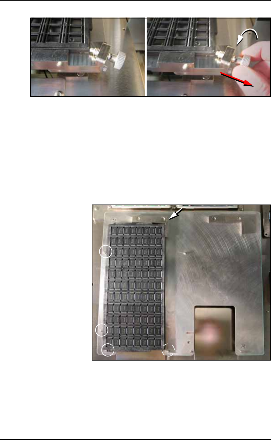
Figure 2-5: To remove a tray, unscrew the thumb screw and lift the tray
out. A second method is NOT RECOMMENDED: pulling the thumb screw
back and holding it away from the tray while lifting the tray out; if the
thumb screw is released too soon, devices may be knocked out of the
tray.
Static Tray Mount with Magnets
To set up the static tray input and output with magnetic brackets:
1. Preparation—
1a. Ensure the PNP head is parked.
1b. Open the front safety shield.
2. Install the Trays—
Figure 2-6: Push trays snug against index pins (circled). Extra pins are
for larger trays. Push the magnetic bracket snug against the tray.
2a. Set the tray onto the mounting plate and snug against the index
pins on two sides.
2b. Place the ‘L’ shaped magnetic bracket against the corner adjacent
to the un-indexed sides.
■ Setting Up Input and Output Media ◘ Install Reject Bin
PS Series Owner’s Manual 2—9
back
Remember that
• the Setup Window > Options tab must be set to match the work-
space setup. This is covered in Chapter 3, Set Media and
Options—the Setup Window.
• The Package File must be taught the Tray locations.
CAUTION: Temporarily removing trays has consequences. Sensors
register a tray’s presence.
If a tray is removed and then returned to the mount while a job is
Paused,
the software proceeds as if: [Input tray] the tray is full
and all devices are unprocessed, and [Output tray] the tray is
empty.
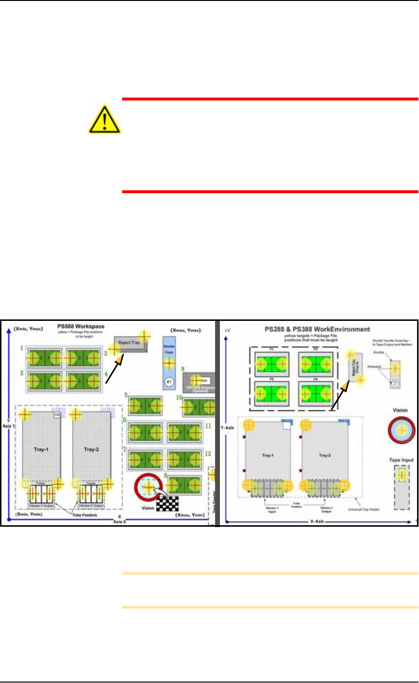
Install Reject Bin
Install a reject container for devices failing any process. Many work-
space layouts are possible. Generally, a Reject Bin or box is placed
near the back center area of the workspace, just to the right of pro-
grammer 2 as shown in Figure 2-7. However, it can be placed wher-
ever there is room for it as long as its location is taught in the Package
File.
Figure 2-7: Common locations for the Reject Bin, PS588 (left) and
PS288 & PS388 (right).
Note: On the Gantry Window, the Reject Bin or Tray is repre-
sented by the yellow position label that reads RTr.
A tray may also be used as a Reject container. Possible layouts are
shown in the following diagram.
8
9
10
11
12