PS288_PS388_PS588_981-0424-002D - 第51页
■ Setting Up Input and Output Media ◘ Install Reject Bin PS Series Owner’s Manual 2—9 back Remember that • t h e Setup Window > Options tab must be set to match the work- space setup. This is covered in Chapter 3, Set…
Setup ■ Setting Up Input and Output Media
2—8 Data I/O • 981-0424-002
back
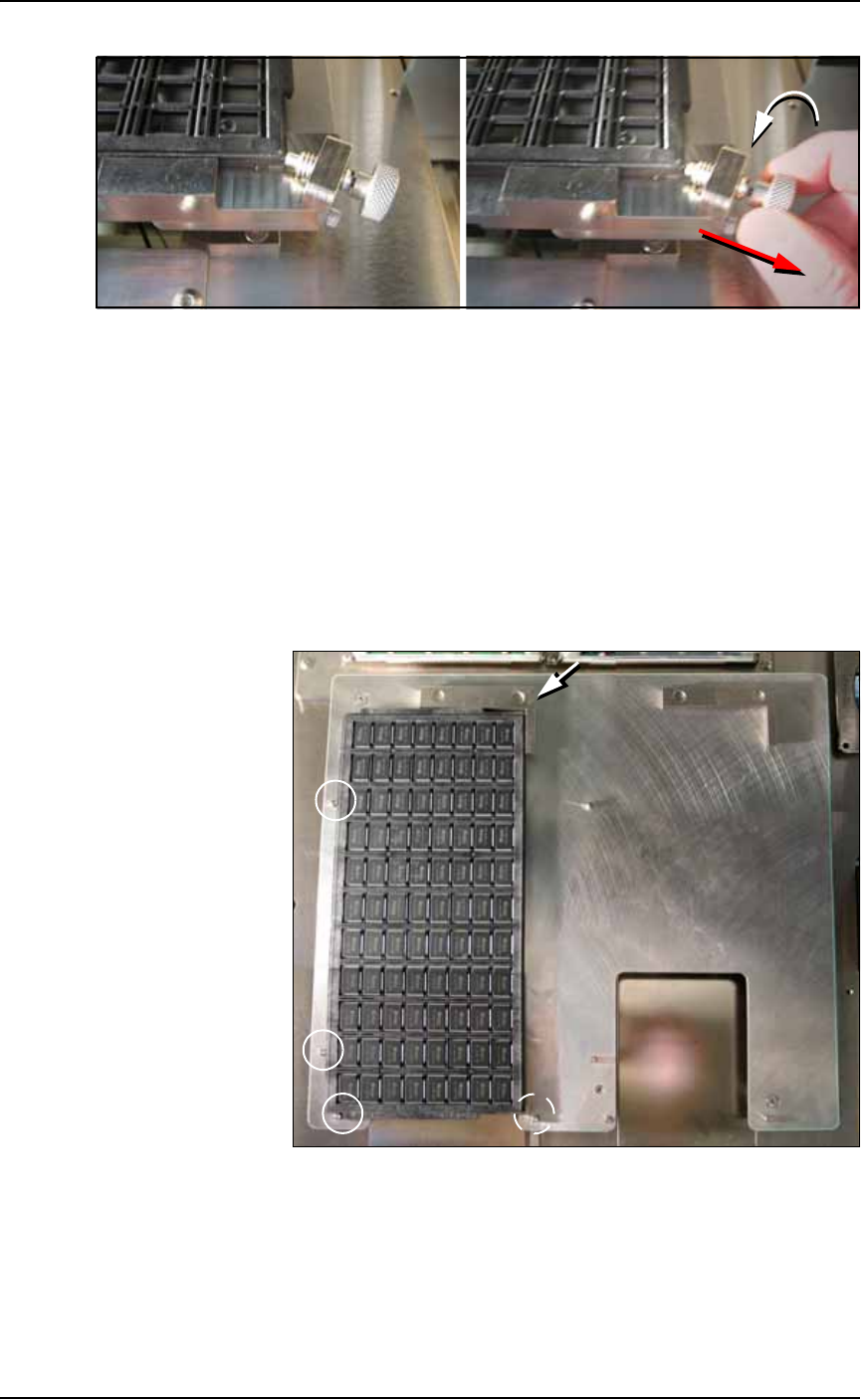
Figure 2-5: To remove a tray, unscrew the thumb screw and lift the tray
out. A second method is NOT RECOMMENDED: pulling the thumb screw
back and holding it away from the tray while lifting the tray out; if the
thumb screw is released too soon, devices may be knocked out of the
tray.
Static Tray Mount with Magnets
To set up the static tray input and output with magnetic brackets:
1. Preparation—
1a. Ensure the PNP head is parked.
1b. Open the front safety shield.
2. Install the Trays—
Figure 2-6: Push trays snug against index pins (circled). Extra pins are
for larger trays. Push the magnetic bracket snug against the tray.
2a. Set the tray onto the mounting plate and snug against the index
pins on two sides.
2b. Place the ‘L’ shaped magnetic bracket against the corner adjacent
to the un-indexed sides.
■ Setting Up Input and Output Media ◘ Install Reject Bin
PS Series Owner’s Manual 2—9
back
Remember that
• the Setup Window > Options tab must be set to match the work-
space setup. This is covered in Chapter 3, Set Media and
Options—the Setup Window.
• The Package File must be taught the Tray locations.
CAUTION: Temporarily removing trays has consequences. Sensors
register a tray’s presence.
If a tray is removed and then returned to the mount while a job is
Paused,
the software proceeds as if: [Input tray] the tray is full
and all devices are unprocessed, and [Output tray] the tray is
empty.
Install Reject Bin
Install a reject container for devices failing any process. Many work-
space layouts are possible. Generally, a Reject Bin or box is placed
near the back center area of the workspace, just to the right of pro-
grammer 2 as shown in Figure 2-7. However, it can be placed wher-
ever there is room for it as long as its location is taught in the Package
File.
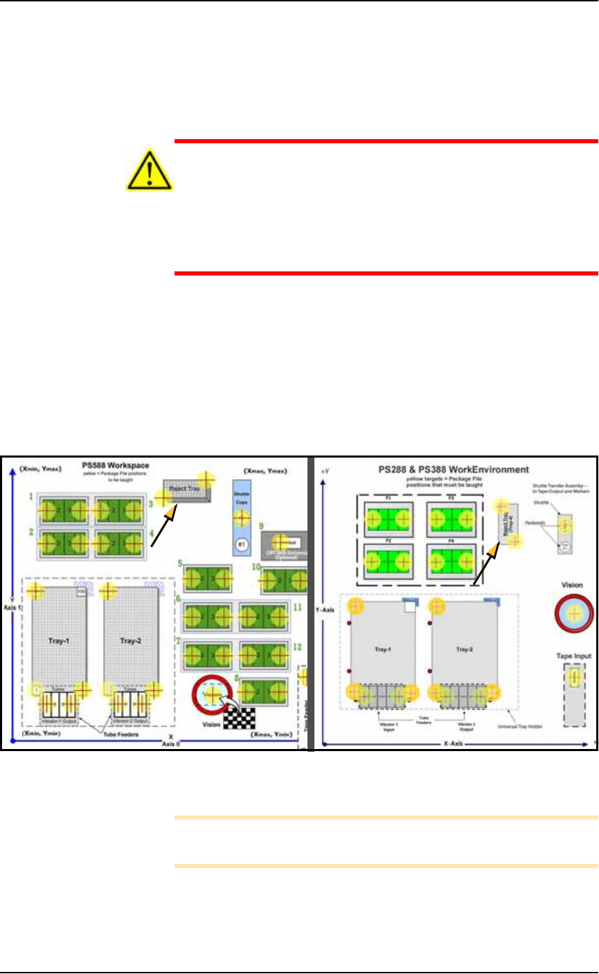
Figure 2-7: Common locations for the Reject Bin, PS588 (left) and
PS288 & PS388 (right).
Note: On the Gantry Window, the Reject Bin or Tray is repre-
sented by the yellow position label that reads RTr.
A tray may also be used as a Reject container. Possible layouts are
shown in the following diagram.
8
9
10
11
12
Setup ■ Setting Up Input and Output Media
2—10 Data I/O • 981-0424-002
back
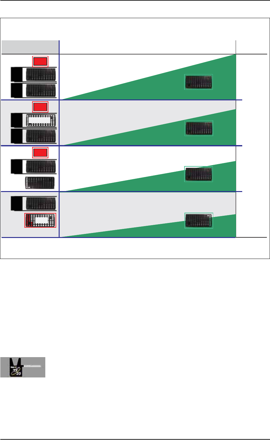
Figure 2-8: Four possible Input/Output layouts with one and two
Automatic Tray Feeders. Only one layout uses a tray for the rejected
devices.
Remember that
•the Setup Window > Options tab must be set to match the work-
space setup. This is covered in Chapter 3, Set Media and
Options—the Setup Window
• The Package File must be taught the location of the Reject con-
tainer.
Setting Up an Automatic Tray Feeder
The PS System can be configured with a TF20 Automatic Tray Feeder.
The Tray Feeder must be level and square to the PS Machine. For gen-
eral information about setting it up, see the Tray Feeder Owner’s
Manual that came with your system. Look for the heading Installation.
TF
20
TF
20
TF
20
TF
20
TF
20
TF
20
Rej
+ Easy to reprocess rejected devices
– Trays may not get completely lled
– A tray jam can cause ambiguity if no
device marking is employed
In/Out
In/Out
Aux. Static
Input
Input
In/Out
In/Out
Output
TRAY ARRANGEMENTS WITH AUTOMATIC TRAY FEEDERS
TIME
QTY
Highest
Throughput
Lowest
Throughput
Output Advantages and Disadvantages
Rej
Rej
Rej
Tray Congurations
T
Throughput
+ Best programmer utilization
– A tray jam can cause ambiguity if no
device marking is employed
+ Fail-safe separation of programmed/unprogrammed devices
– Requires the most trays
+ Best throughput with one Automatic Tray Feeder
– A tray jam can cause ambiguity if no
device marking is employed