PS288_PS388_PS588_981-0424-002D - 第54页
Setup ■ Setting Up Input and Output Media 2—12 Data I/O • 981-0424 -002 back Figure 2-10: P ossible Spare T ray conf igurations in the Setup > Opt ions Window . Only T ray 2 can be designat ed as a spare tra y . Setti…
■ Setting Up Input and Output Media ◘ Setting Up an Automatic Tray Feeder
PS Series Owner’s Manual 2—11
back
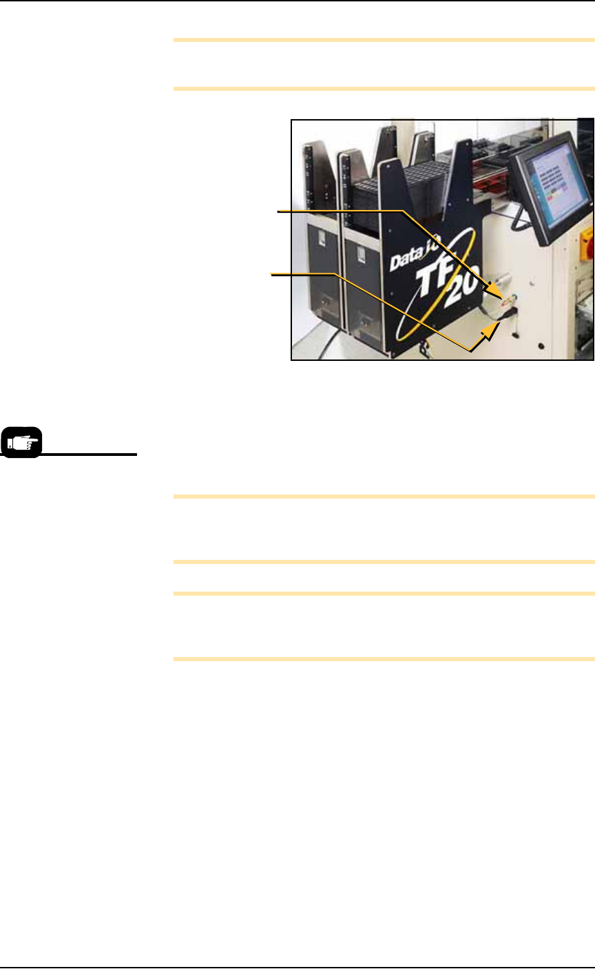
Note: Due to variations, detailed instructions are supplied with
each mounting kit.
Figure 2-9: Two TF20 Automatic Tray Feeders on a PS588. Arrows
point to the connections for one of them.
The winAH400.ini file requires editing prior to using an Automatic
Tray Feeder if your PS Machine has not already been set up for Auto-
matic Tray Feeders at the factory. See the on-screen Help file for topic
Editing the WinAH400.ini file.
Note: On some models, your Setup > Options Window does not
indicate whether Tray 1 and/or Tray 2 are Static Trays or Auto-
matic Tray Feeders.
Note: When your winAH400.ini file is set to run Automatic Tray
Feeders, before you can run static trays again, the file will need to
be changed back to ModelTray1=STD.
Basic operating instructions are covered in Chapter 3 of this manual.
Spare Tray Configurations
You can use a static tray with an Automatic Tray Feeder (ATF). When
tray 2 is designated as a spare static tray, the devices from that spare
tray are used to replace rejected devices. They are also used as a
buffer during a tray change. This allows the Tray Feeder to exchange
trays only when full. (Without the spare tray, the Tray Feeder will
exchange trays with empty pockets.) For possible configurations, see
the chart on the following page.
Air hose
quick-connect
Electrical
connection
Prior to editing the
winAH400.ini file, make a
backup copy.
Setup ■ Setting Up Input and Output Media
2—12 Data I/O • 981-0424-002
back
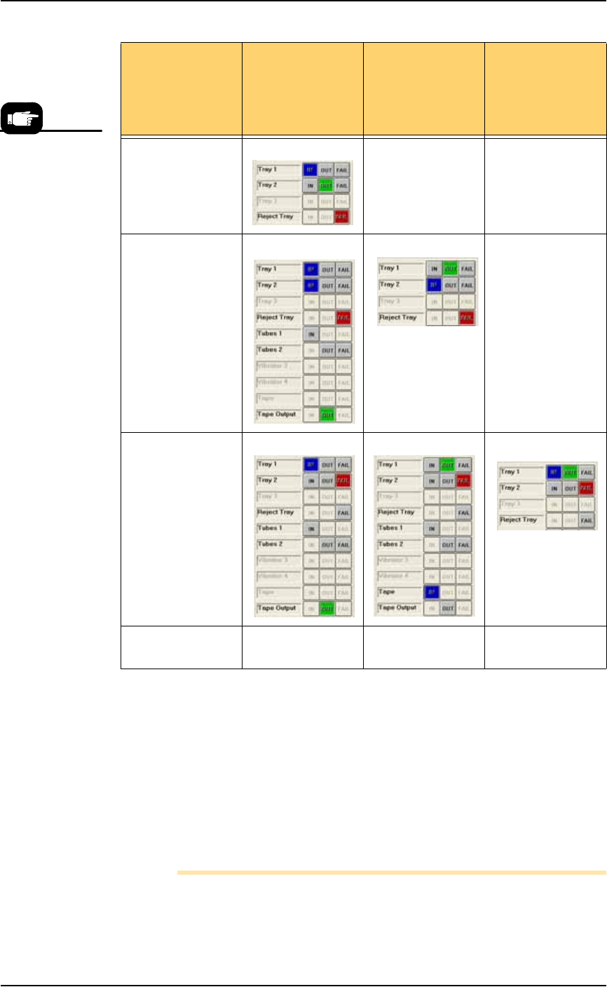
Figure 2-10: Possible Spare Tray configurations in the Setup > Options
Window. Only Tray 2 can be designated as a spare tray.
Setting Up the Tube Input and Output
Media
As an option, the PS System can be configured with tube input and
tube output media. Prior to starting this procedure, turn off the
machine; see Turning Off System Power on page 3-27.
Note: The Data I/O Tube Feeder Option, which includes two
motors and different front panel with control knobs, must already
If your ATF(s) is
set up as
configurations
possibilities
Tray 1 is ATF
IN
Tray 1 as ATF
OUT
Tray 1 as ATF
IN & OUT
Spare tray as OUT XX
Spare tray as IN X
Spare tray as
Reject
Spare tray as IN &
OUT
X XX
If you wish to set
Tray 1 as ATF
FAIL, contact Data
I/O Customer
Support or a local
Data I/O
approved service
representative.
■ Setting Up Input and Output Media ◘ Setting Up the Tube Input and Output Media
PS Series Owner’s Manual 2—13
back
be installed in the PS System. If it is not, contact Data I/O Cus-
tomer Support or a local Data I/O approved service representative.
To set up the tube input and tube output media:
1. Determine the size of the devices to be programmed and select
tubes and platform that match device size.
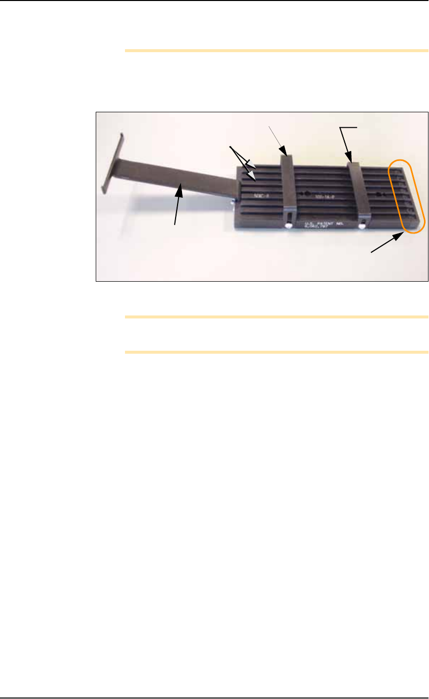
Figure 2-11: Input tube loader platform. (The tubes are not installed).
Note: You can perform Step 3 before Step 2 if it is more convenient
for you.
2. Install the loader platform—
2a. Open the front safety shield and install the input tube loader
platform onto the input Vibrator Motor 1 (Vib1) on the left side
of the workspace. See Figure 2-12.
2b. Tighten the two screws using a 9/64 inch hex key.
Rear tube guide
Front tube
guide
Tube elevator
Lanes
Pick location
(staging area)