PS288_PS388_PS588_981-0424-002D - 第55页
■ Setting Up Input and Output Media ◘ Setting Up the Tube Input and Output Media PS Series Owner’s Manual 2—13 back be installed in the PS System. If it is not, contact Data I/O Cus- tomer Support or a local Data I/O app…
Setup ■ Setting Up Input and Output Media
2—12 Data I/O • 981-0424-002
back
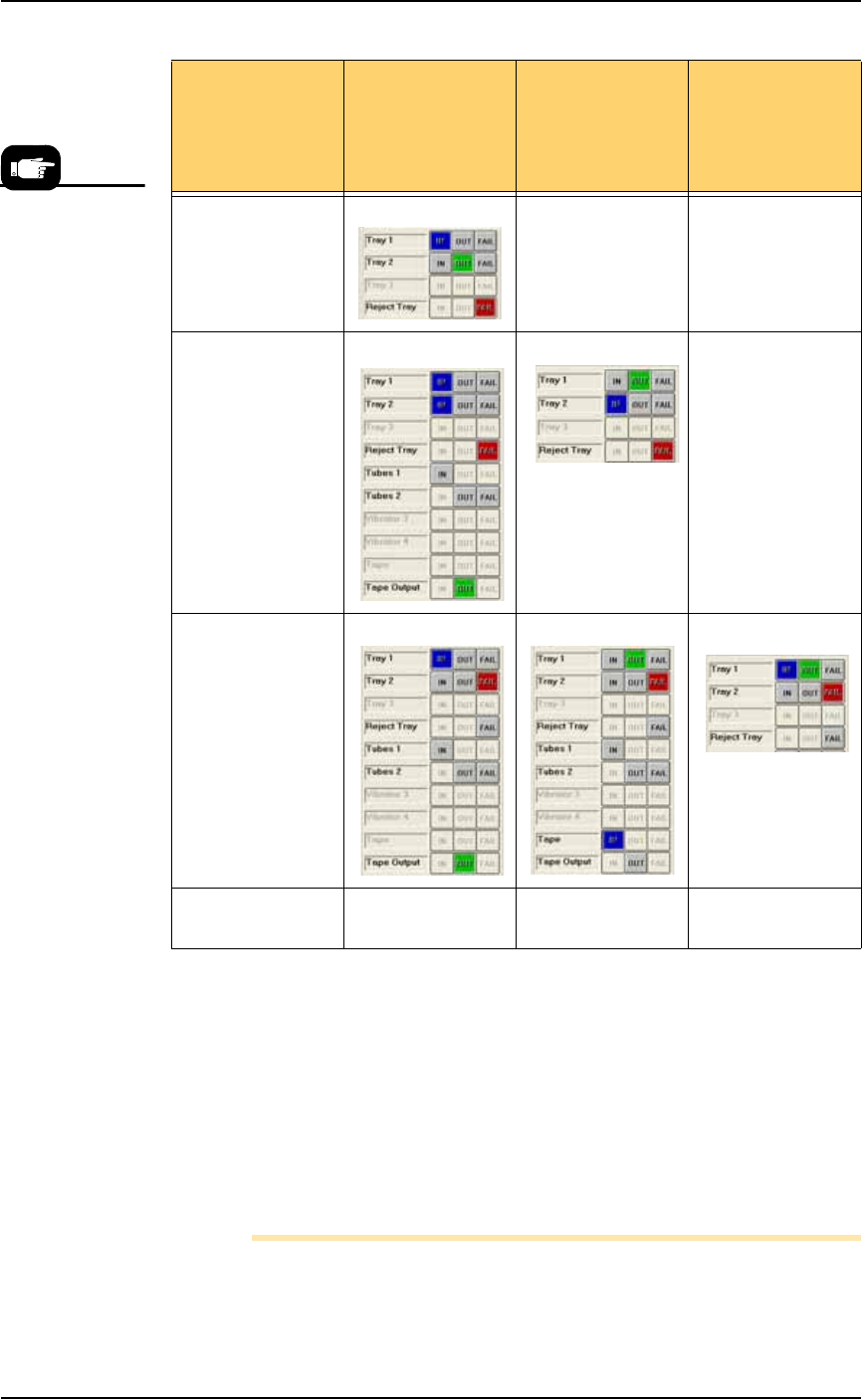
Figure 2-10: Possible Spare Tray configurations in the Setup > Options
Window. Only Tray 2 can be designated as a spare tray.
Setting Up the Tube Input and Output
Media
As an option, the PS System can be configured with tube input and
tube output media. Prior to starting this procedure, turn off the
machine; see Turning Off System Power on page 3-27.
Note: The Data I/O Tube Feeder Option, which includes two
motors and different front panel with control knobs, must already
If your ATF(s) is
set up as
configurations
possibilities
Tray 1 is ATF
IN
Tray 1 as ATF
OUT
Tray 1 as ATF
IN & OUT
Spare tray as OUT XX
Spare tray as IN X
Spare tray as
Reject
Spare tray as IN &
OUT
X XX
If you wish to set
Tray 1 as ATF
FAIL, contact Data
I/O Customer
Support or a local
Data I/O
approved service
representative.
■ Setting Up Input and Output Media ◘ Setting Up the Tube Input and Output Media
PS Series Owner’s Manual 2—13
back
be installed in the PS System. If it is not, contact Data I/O Cus-
tomer Support or a local Data I/O approved service representative.
To set up the tube input and tube output media:
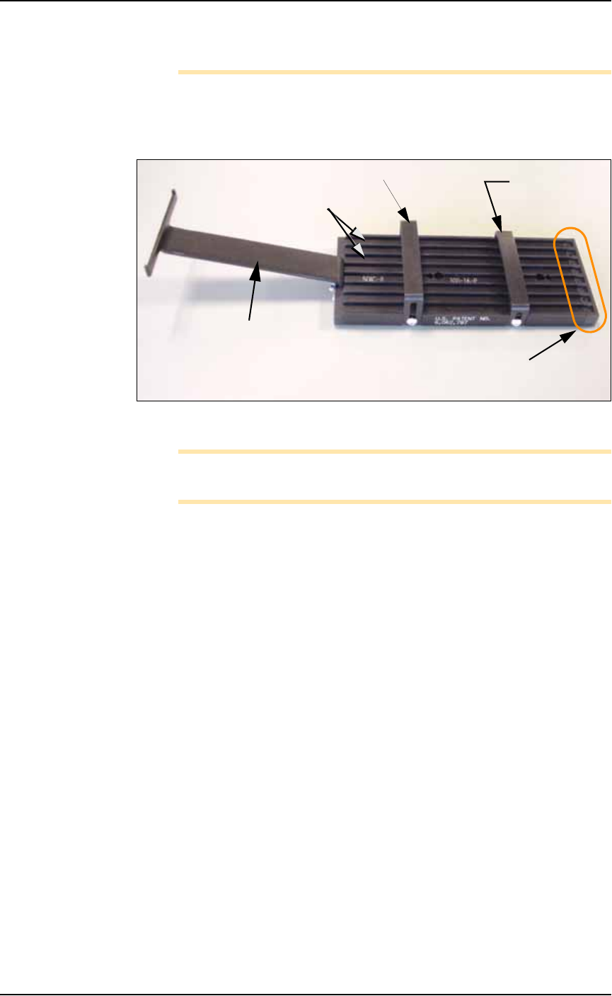
1. Determine the size of the devices to be programmed and select
tubes and platform that match device size.
Figure 2-11: Input tube loader platform. (The tubes are not installed).
Note: You can perform Step 3 before Step 2 if it is more convenient
for you.
2. Install the loader platform—
2a. Open the front safety shield and install the input tube loader
platform onto the input Vibrator Motor 1 (Vib1) on the left side
of the workspace. See Figure 2-12.
2b. Tighten the two screws using a 9/64 inch hex key.
Rear tube guide
Front tube
guide
Tube elevator
Lanes
Pick location
(staging area)
Setup ■ Setting Up Input and Output Media
2—14 Data I/O • 981-0424-002
back
Figure 2-12: Vibrator motors Vib1, on the left, and Vib2, right. Arrows
point to screws for attaching tube platforms.
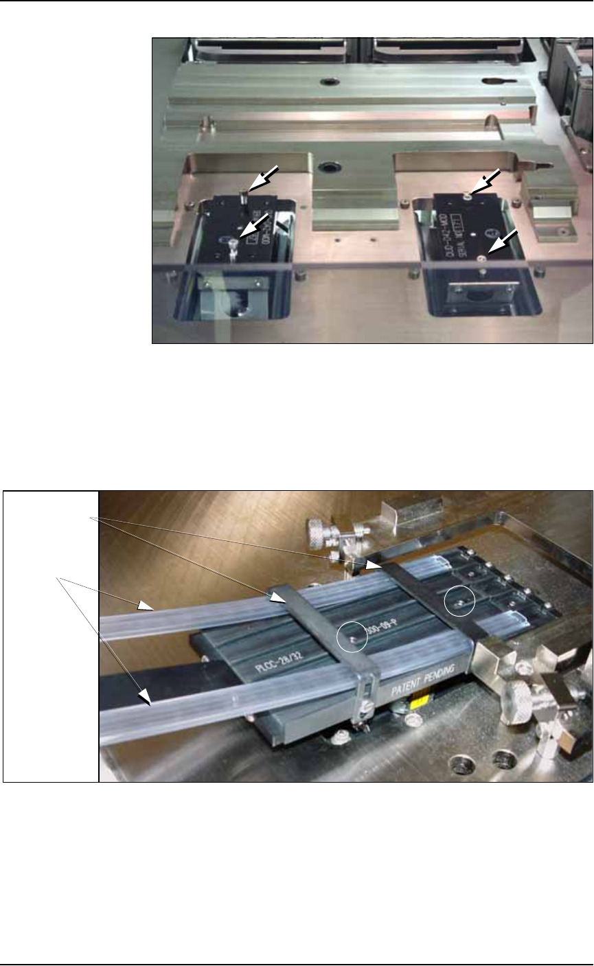
3. Adjust the tube guides on the input tube platform—
3a. Temporarily insert empty tubes in the first and last lanes of the
input tube loader platform. See Figure 2-13.
3b. Adjust the tube guides so the tubes are attached to the platform
snugly but are not compressed out of shape.
Figure 2-13: Adjust the front and rear tube guides with two empty
tubes installed. Platform mounting screws are circled. Tray mounts
(with thumb screws) need not be removed from the work surface.
3c. Remove the empty tubes from the input tube loader platform.
4. Adjust the output tube unloader platform tube guides as
described in Step 3 above.
Front & Rear
Tube Guides
Tubes