PS288_PS388_PS588_981-0424-002D - 第57页
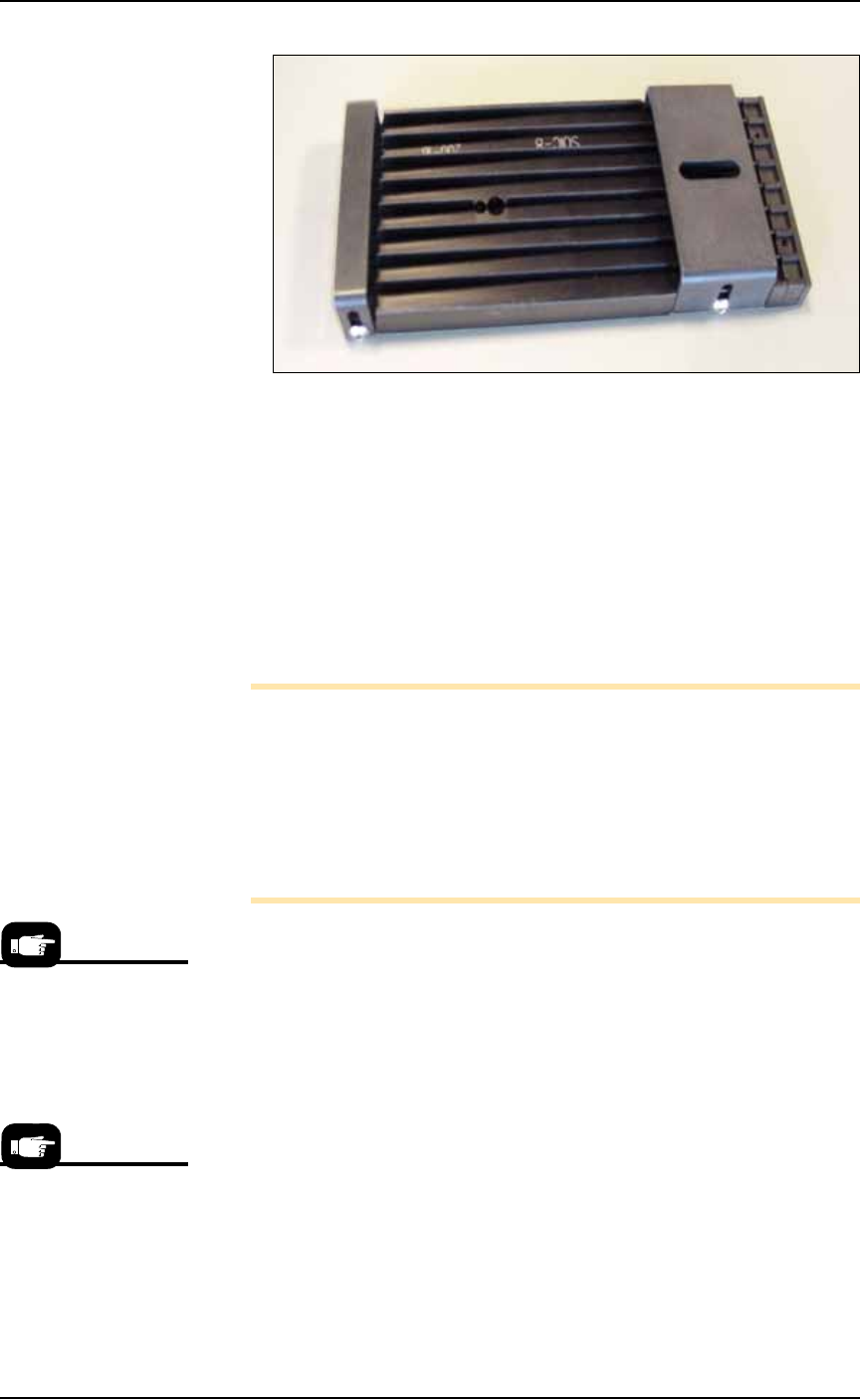
■ Setting Up Input and Output Media ◘ Setting Up the Tube Input and Output Media PS Series Owner’s Manual 2—15 back Figure 2-14: Output tube unloader platform. 5. Install output tube unloader platform— 5a. Install the ou…
Setup ■ Setting Up Input and Output Media
2—14 Data I/O • 981-0424-002
back
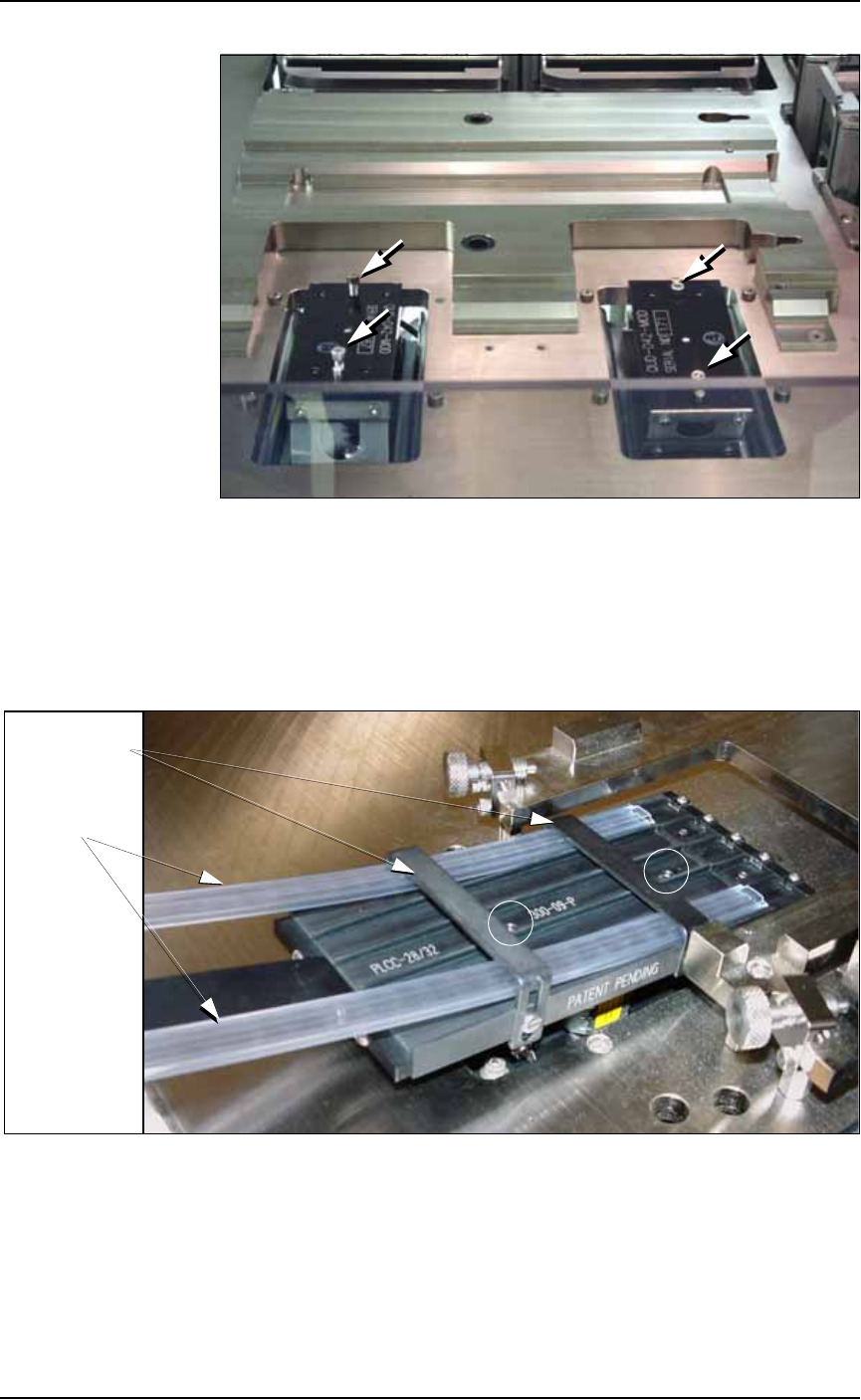
Figure 2-12: Vibrator motors Vib1, on the left, and Vib2, right. Arrows
point to screws for attaching tube platforms.
3. Adjust the tube guides on the input tube platform—
3a. Temporarily insert empty tubes in the first and last lanes of the
input tube loader platform. See Figure 2-13.
3b. Adjust the tube guides so the tubes are attached to the platform
snugly but are not compressed out of shape.
Figure 2-13: Adjust the front and rear tube guides with two empty
tubes installed. Platform mounting screws are circled. Tray mounts
(with thumb screws) need not be removed from the work surface.
3c. Remove the empty tubes from the input tube loader platform.
4. Adjust the output tube unloader platform tube guides as
described in Step 3 above.
Front & Rear
Tube Guides
Tubes
■ Setting Up Input and Output Media ◘ Setting Up the Tube Input and Output Media
PS Series Owner’s Manual 2—15
back
Figure 2-14: Output tube unloader platform.
5. Install output tube unloader platform—
5a. Install the output tube unloader platform onto the output Vibra-
tor Motor 2 (Vib2) on the right side of the workspace. Vibrator
Motor 2 is shown in Figure 2-12.
5b. Tighten the two screws using a 9/64 inch hex key.
6. Insert tubes—
6a. Insert full tubes into the input tube loader platform.
6b. Insert empty tubes into the output tube unloader platform.
6c. Close the safety shield.
Note: Ensure that blank devices are loaded into the input tubes
with the correct pin 1 orientation. If pin 1 orientation doesn’t
match pin 1 on the sockets, the correct rotation much be taught in
the Package file.
Pin 1 on Data I/O sockets is almost always toward the far side of
the adapter (the back of the PS Machine). Some BGAs and PLCCs
are marked.
7. Edit the winAH400.ini file for tube feeders—
7a. Using Windows Explorer, locate
C:\AH500\winAH400.ini
and m
ake a backup copy, for example,
WinAH400backup.ini
.
7b. Open the original file with Microsoft Notepad.
7c. Locate the line
TubeFeeder1=FALSE
and change to
TubeFeeder1=STDIN
7d. Locate the line
TubeFeeder2=FALSE
and change to
TubeFeeder2=STDOUT
7e. Save the
winAH400.ini
file and exit Windows Explorer.
If you have previously
used Tube Feeders you
may already have saved
a winAH400.ini file spe-
cifically for a Tube
Feeder setup.
See the on-screen Help
for more ini file infor-
mation.
Setup ■ Setting Up Input and Output Media
2—16 Data I/O • 981-0424-002
back
8. Adjust vibration controls—
8a. If devices do not travel freely in either tube, adjust the vibration
using the Amplifier and Frequency controls on the front panel of
the PS Machine.
Remember
•The Setup Window > Options tab must be set to match the work-
space setup. This is covered in Chapter 3, Set Media and
Options—the Setup Window.
• The Package File must be taught the Tube locations.
Setting Up the Tape Feeder Input
The PS System can be configured with an optional tape feeder for
input media. The tape feeder is installed on the front of the
PS Machine.
To install a Tape Feeder for input:
1. Preparation—
1a. At the monitor, stop any job that is running and exit the AH500
Application.
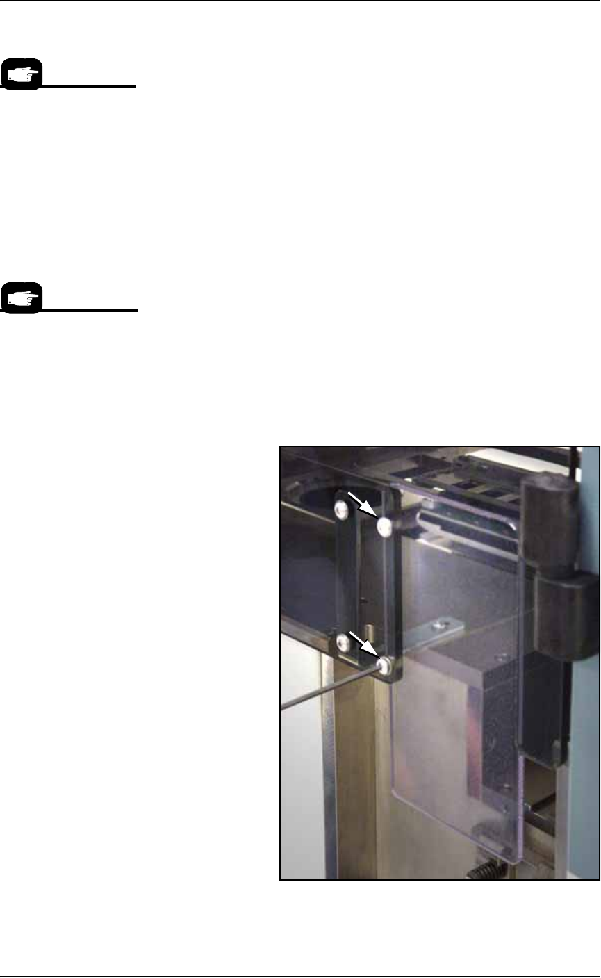
1b. Remove the two screws holding the small safety shield that cov-
ers the tape input feeder slot at the front of the PS Machine.
Figure 2-15: Two screws holding the small safety shield. [PS588
shown.]
On the Gantry Window,
the Tube Feeders are rep-
resented by the yellow
position labels that reads
Vib1 and Vib2.
Tape input feeders are
available in sizes to
match common device
tape widths. The last two
digits of the tape input
feeder part number indi-
cate the tape width.