PS288_PS388_PS588_981-0424-002D - 第59页
■ Setting Up Input and Output Media ◘ Setting Up th e Tape Feeder Input PS Series Owner’s Manual 2—17 back 1c. Remove the small safety shield and set it aside with the screws. It is not used when the tape input feeder un…
Setup ■ Setting Up Input and Output Media
2—16 Data I/O • 981-0424-002
back
8. Adjust vibration controls—
8a. If devices do not travel freely in either tube, adjust the vibration
using the Amplifier and Frequency controls on the front panel of
the PS Machine.
Remember
•The Setup Window > Options tab must be set to match the work-
space setup. This is covered in Chapter 3, Set Media and
Options—the Setup Window.
• The Package File must be taught the Tube locations.
Setting Up the Tape Feeder Input
The PS System can be configured with an optional tape feeder for
input media. The tape feeder is installed on the front of the
PS Machine.
To install a Tape Feeder for input:
1. Preparation—
1a. At the monitor, stop any job that is running and exit the AH500
Application.
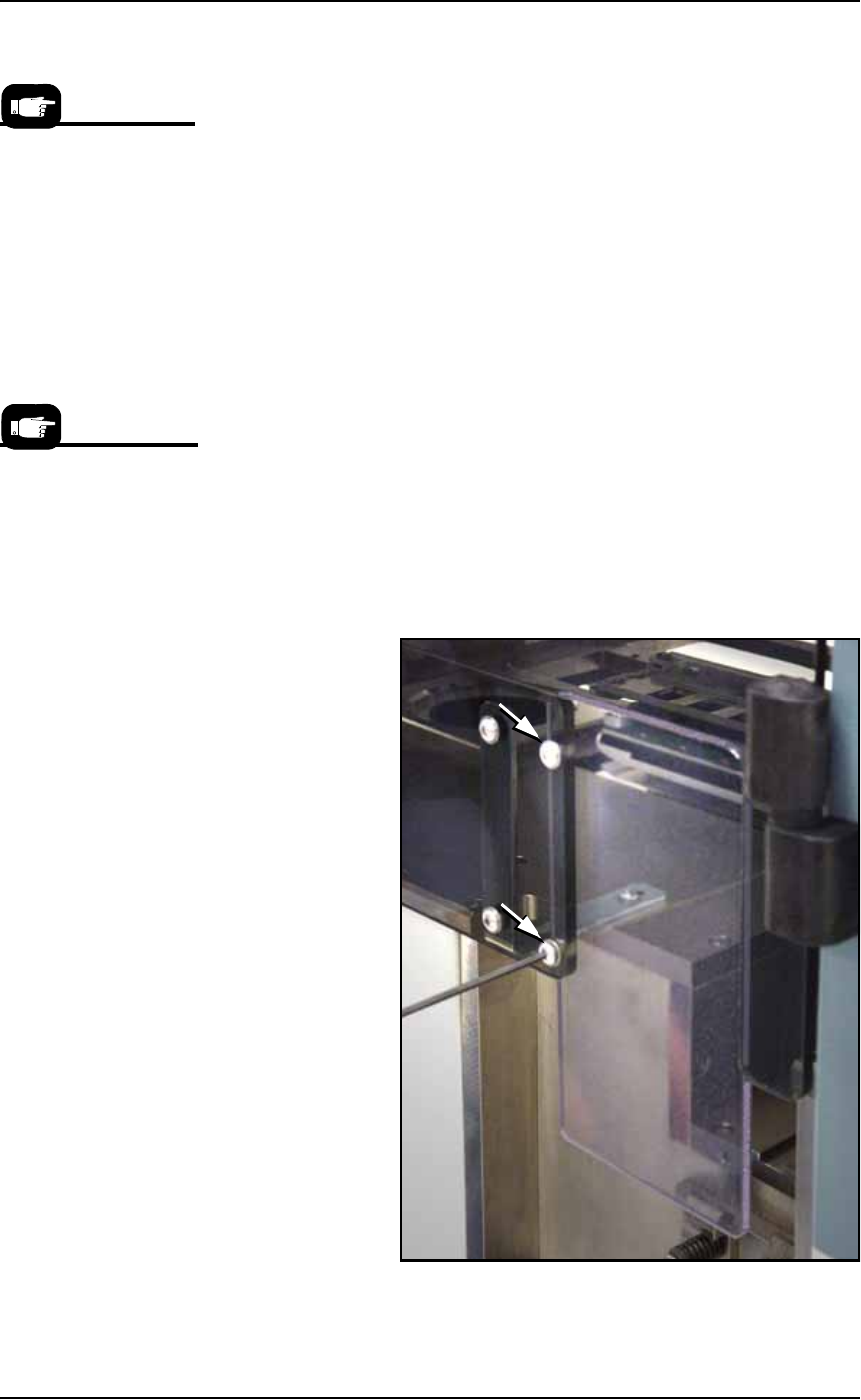
1b. Remove the two screws holding the small safety shield that cov-
ers the tape input feeder slot at the front of the PS Machine.
Figure 2-15: Two screws holding the small safety shield. [PS588
shown.]
On the Gantry Window,
the Tube Feeders are rep-
resented by the yellow
position labels that reads
Vib1 and Vib2.
Tape input feeders are
available in sizes to
match common device
tape widths. The last two
digits of the tape input
feeder part number indi-
cate the tape width.
■ Setting Up Input and Output Media ◘ Setting Up the Tape Feeder Input
PS Series Owner’s Manual 2—17
back
1c. Remove the small safety shield and set it aside with the screws.
It is not used when the tape input feeder unit is installed.
2. Edit the winAH400.ini file for Tape Feeder Input—
2a. Using Windows Explorer, locate
C:\AH500\winAH400.ini
and m
ake a backup copy, for example,
WinAH400backup.ini
.
2b. Open the original file with Microsoft Notepad.
Locate the line
TapeAdvanceInstalled=FALSE
and change to
TapeAdvanceInstalled=TRUE
2c. Save the
winAH400.ini
file and exit Windows Explorer.
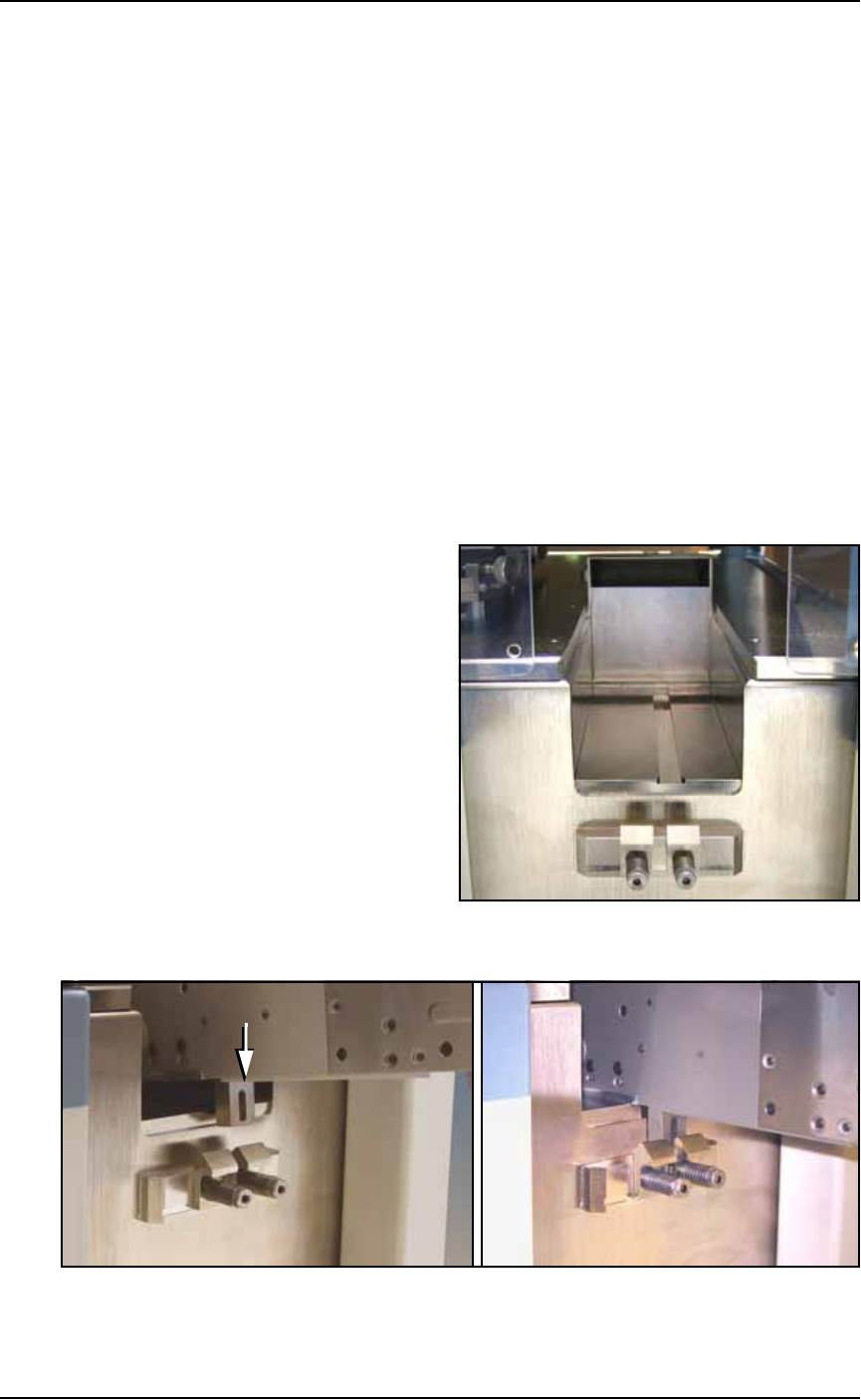
3. Mount the feeder unit—
3a. Align the rail on the bottom of the feeder with the channel on the
PS Machine base plate.
3b. With the feeder in the channel, slide it toward the back. When
the feeder reaches the spring latches, lift it over to the far side of
the latches and push down to secure.
If tape is already loaded on the feeder, ensure it gets started
down the chute in the workspace. See Figure 2-16.
Figure 2-16: The channel and spring clamps on the PS Machine.
Figure 2-17: Push the mounting block of the Feeder into the spring
clamp.
Setup ■ Setting Up Input and Output Media
2—18 Data I/O • 981-0424-002
back
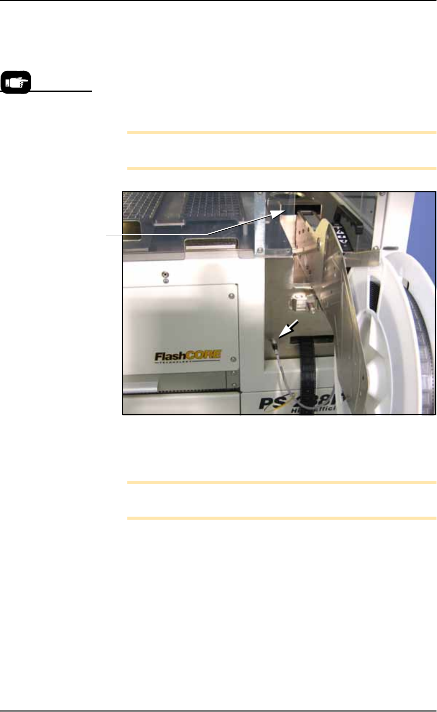
4. Connect cable—
4a. Insert the communication cable part way into the socket on the
PS Machine and, while pushing lightly, rotate until the connec-
tor is oriented correclty—it will stop and even make a slight
click sound.
4b. Push the rest of the way on. The Status lamp should light if the
PS System is on.
4c. Install the device reel if it is not already.
Note: For more information about loading a reel of devices onto the
feeder, see the documentation that came with your tape feeder.
Figure 2-18: The Tape-Input cable is plugged into the front of the
PS Machine. (PS288 shown.)
5. Thread the carrier tape through the feeder.
Note: For more information about threading carrier tape, see the
documentation that came with your tape feeder.
5a. Pull the carrier tape forward to start it into the carrier waste tape
chute. See Figure 2-18.
The empty device carrier tape will come out of the slot below the
mounting latch. Place a box on the floor to contain empty carrier
tape.
6. Thread cover tape through the tape window and onto the
feeder’s cover tape roller.
To remove the Tape
Feeder communication
cable, grasp the collar
and pull out.
Carrier tape
waste chute on
the PS Machine.