PS288_PS388_PS588_981-0424-002D - 第63页
■ Setting Up Input and Output Media ◘ Setting Up the Tape Output Sys tem PS Series Owner’s Manual 2—21 back 2a. The T ape Output System gets power and compressed air from the PS System. Ensure the PS Syst em air is conne…
Setup ■ Setting Up Input and Output Media
2—20 Data I/O • 981-0424-002
back
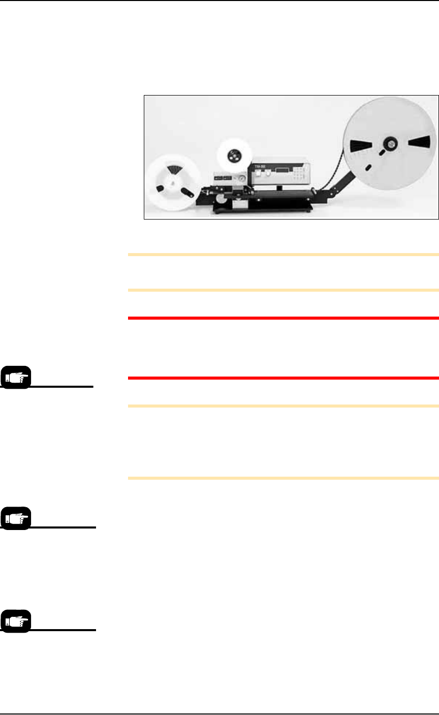
The tape output system receives programmed devices from the
PS System via a second PNP head on the output frame. With this
head, the Tape Output System places devices into empty carrier tape
pockets, advances the carrier tape through a mechanism that seals the
tape (using heat or pressure), and rolls the filled tape onto a reel for
delivery to the next stage in the manufacturing process.
Figure 2-20: Tape Output System.
Note: For additional information, refer to the TM-50 SMD Taping
Module User’s Guide that came with your Tape Output System.
CAUTION: Excessive Heat. Improper routing of the device tape
may cause enough heat to melt the tape. Ensure the correct rout-
ing path is followed. See the TM-50 SMD Taping Module User’s
Guide.
Note: The Tape Out System includes the Option Bay, the shuttle
transfer, and the Tape-Out-PNP head. These must already be
installed on the PS Machine before following the setup instructions
below. If it is not, contact Data I/O Customer Support or a local
Data I/O approved service representative.
To set up the Tape Output System:
1. Edit the winAH400.ini file for Tape Output—
1a. Using Windows Explorer, locate
C:\AH500\winAH400.ini
and m
ake a backup copy, for example,
WinAH400backup.ini
.
1b. Open the original file with Microsoft Notepad.
1c. Locate the line:
TapeOutPutInstalled=FALSE
and change it to True:
TapeOutputInstalled=TRUE
1d. Save the
winAH400.ini
file and exit Windows Explorer.
2. Preparation—
The information that
follows is adapted from
the TM-50 SMD Tap-
ing Module User’s
Guide that came with
your Tape Output Sys-
tem.
If you have previously
used Tape Output, you
may already have saved
a winAH400.ini file spe-
cifically for a Tape Out-
put setup.
For more ini file infor-
mation, see the
on-screen Help.
■ Setting Up Input and Output Media ◘ Setting Up the Tape Output System
PS Series Owner’s Manual 2—21
back
2a. The Tape Output System gets power and compressed air from
the PS System. Ensure the PS System air is connected and power
is On.
2b. Switch the Tape Output System ON by pulling out its
Power/E-stop button.
2c. Turn the take-up reel tension adjust knob counterclockwise to
zero. (Black knob on the controller.)
2d. Set the taping job parameters at the controller. For more infor-
mation see the TM-50 SMD Taping Module User’s Guide, chap-
ter 3, Controller.
3. Pull the nearest half of the track (table) out to the desired track
width. It stops at detents set to specific tape widths.
4. Mount the carrier tape reel—
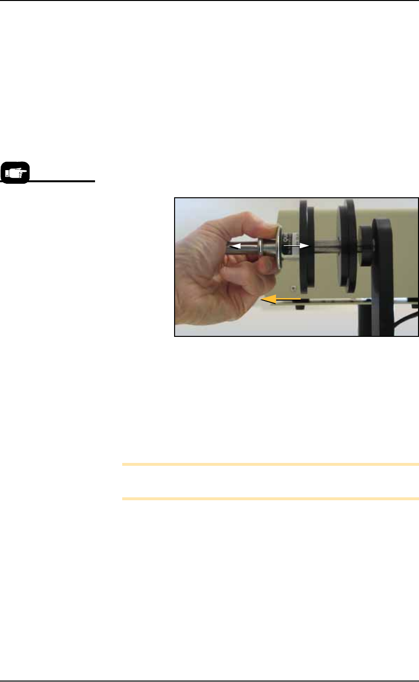
4a. Remove the carrier tape quick lock from the carrier tape spindle.
Figure 2-21: Removing the spindle QuickLock.
4b. Mount the bulk carrier tape reel on the right spindle so the tape
unwinds from the top.
4c. Replace the quick lock.
4d. Trim the end of the carrier tape so it is clean and straight.
5. Route the carrier tape—
5a. Guide the carrier tape into the loading track. It should feed right
to left through the loading track easily.
Note: Lowering the feed reel support arm can reduce drag if the
angle at which the carrier enters the loading track is too steep.
5b. Bring the end of the carrier tape past the sealer and engage the
sprocket holes on the teeth of the drive sprocket.
If the carrier tape does not feed to the sprocket easily, see the
TM-50 SMD Taping Module User’s Guide, Chapter 4, Setup,
Route the Carrier Tape for items to check.
6. Mount the cover tape—
6a. Place a reel of cover tape of the correct width to match the carrier
tape on the cover tape spindle. The tape should unwind to the
right from the bottom of the reel.
For more information
about these steps, see the
TM-50 SMD Taping
Module User’s Guide.

Setup ■ Setting Up Input and Output Media
2—22 Data I/O • 981-0424-002
back
6b. Set the width of the cover tape guide assembly for your size
tape.
6c. Use the Cover Tape Position Adjuster if needed. Turning it clock-
wise moves the cover tape position toward the sprocket side of
the tape.
6d. Using blue tabbing tape, attach the cover tape to the carrier tape.
Thread both through the cover tape Guide Sealer Assembly. Run
the machine to advance the carrier and cover tapes through the
sealer.
Prepare the Seal Method
For heat seal, complete Step 1 below.
For pressure seal (PSA), complete Step 2 below.
1. To prepare the heat seal—
1a. Turn the heat seal toggle switch ON.
Note: Disable the pressure seal by loosening the seal roller pressure
screws until the seal rollers are no longer in contact with the cover
tape.
1b. Set the temperature controls to the appropriate temperature. See
the table below.
Figure 2-22: Tape Output suggested temperature and pressure
settings. The temperature of each shoe can be increased or decreased
according the results of a peel force test.
1c. Adjust the heat shoe air pressure to the appropriate setting. This
setting controls the amount of force applied when the sealer
shoes drop.
Note: The recommended starting point for heat shoe air pressure is
50 PSI. Turning the heat shoe adjuster clockwise increases the pres-
sure.
1d. After the heat sealer reaches operating temperature, set the con-
troller parameters, if not already set.
Heat Seal only
Carrier Tape Type Cover Tape Type Temperature Air Pressure Dwell Time
3m Type 3000
Conductive Carrier
3m Type 2675 Static
Dissipative Cover
135-155°C 40-60 PSI 250-400 ms
3m Type 2701/2703
Non-conductive
Advantek Conductive Advantek Type AA
Advantek
Non-conductive
Advantek Type S