PS288_PS388_PS588_981-0424-002D - 第66页
Setup ■ Setting Up Input and Output Media 2—24 Data I/O • 981-0424 -002 back 3. Create the T railer and Leader Before beginning a production reel, determine how long the trailer and the leader should be. Run out enough s…

■ Setting Up Input and Output Media ◘ Setting Up the Tape Output System
PS Series Owner’s Manual 2—23
back
Note: For additional information, refer to the TM-50 SMD Taping
Module User’s Guide, Chapter 3, Controller.
1e. Set the Controller to RUN mode.
1f. Advance the tape using the foot switch.
1g. Check the sealed tape for the desired sealed position.
1h. If necessary, adjust the inner seal position by turning the inner
seal adjuster (thumb wheel) clockwise (to move the seal away
from the operator) or counterclockwise. Tighten the position
lock to secure it.
1i. If necessary, adjust the outer seal position by turning the outer
seal adjuster (thumb wheel) clockwise to move the seal toward
the operator or counterclockwise (to move the seal away from
the operator). Lock the adjuster into place using the position
lock knob.
2. To prepare the pressure seal—
Note: If the heat sealer is On, turn it OFF.
2a. Set the controller for Pressure Sensitive Adhesive (PSA) opera-
tion. Refer to the Chapter 3, Controller of the TM-50 SMD Taping
Module User’s Guide. Then set the controller to RUN mode.
Note: When RUN is selected, the controller is ready to operate. The
parameters which have been entered are displayed on the screen
along with the running devices count. The controller will begin to
advance and seal tape when the foot switch is pressed.
2b. Advance the tape using the foot switch.
2c. Adjust the inner and outer seal roller position. Align the roller
position over the strip of adhesive on either side of the PSA
cover tape. Both thumb screws have locking devices.
2d. Adjust the pressure at both sealer wheels to free spinning and
then 1/8 revolution tighter. Use a 2 mm hex key.
2e. Advance the tape using the foot switch. Re-adjust the seal roller
pressure until the PSA adhesive is firmly adhered to the carrier
tape.
Note: Excessive roller pressure may cause carrier tape advance
problems or elongation of sprocket holes in the carrier tape.
Checks to Perform Prior to Running
1. Mount an empty take-up reel on the spindle.
2. Perform a Peel Force Test
Perform as many peel force tests as needed while adjusting the
sealer controls to obtain the required seal strength.
Pressure Seal
only
Setup ■ Setting Up Input and Output Media
2—24 Data I/O • 981-0424-002
back
3. Create the Trailer and Leader
Before beginning a production reel, determine how long the
trailer and the leader should be. Run out enough sealed empty
pockets to make the trailer that is required for the current job.
4. Check Carrier Tape Alignment
To ensure an accurate count, select a spot on the loading track as
a reference point for the first and last devices counted.
5. Set the Counter
Set the counter STOP value in the controller menu to zero.
Note: Use the counter on the TM-50 if desired. However, we rec-
ommend setting this counter to zero and using the pass quantity on
the PS System to monitor quantity.
Preparing the Tape-Output-PNP Head
It is necessary to accurately position the Tape-Output-PNP head over
the carrier tape so that devices are placed properly.
1. Adjust location of PNP head—
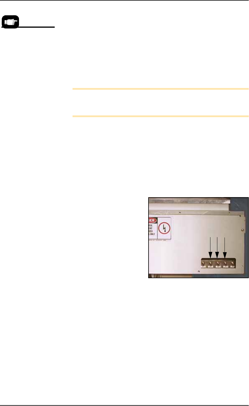
1a. On the PLC Controller:
• Flip the Transfer toggle DOWN
• Flip the Long Stroke toggle DOWN
• Flip the Short Stroke toggle DOWN
Figure 2-23: Toggle switches in DOWN position
1b. On the Tape Output Controller select
6
for Jog. This advances
the carrier tape in 0.04 mm increments.
Continue to press
6
for Jog until the center of the empty pocket
is directly beneath the PNP head.
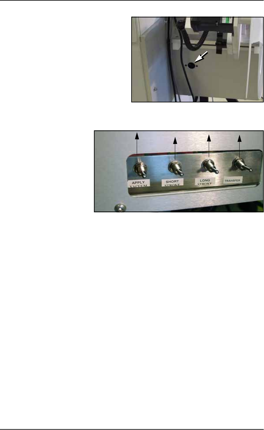
1c. On the PLC Controller, press the black reset button located on its
left side.
Remember, when the
reel is being taped on
the TM-50, the trailer is
the first length of empty
carrier tape run before
the first device is taped,
and the leader is the
length of empty carrier
tape run after the last
device is taped.
■ Setting Up Input and Output Media ◘ Setting Up the Tape Output System
PS Series Owner’s Manual 2—25
back
Figure 2-24: The Reset button on the PLC Controller.
1d. On the front of the controller, flip all toggles UP.
Figure 2-25: Toggle switches should be in UP (normal) position
1e. On the Tape Output Controller, press ESC to enter RUN mode.
The Tape Output System is now ready for programmed devices.
Placing Devices
Devices are placed by the Tape-Out-PNP head when your PS job is
run.
Ending a Taped Run
When all components have been taped or the batch size has been
reached, perform the following:
1. Reset the counter to zero and run out the amount of empty car-
rier tape needed to make the leader.
2. Cut the carrier tape and cover tape.
Replacing a Full Take Up Reel
1. Leave job-specified number of empty pockets on the carrier tape.
2. Cut the carrier tape.
3. Roll carrier tape onto take up reel and remove reel.
4. Install empty take up reel.
5. Continue job.