PS288_PS388_PS588_981-0424-002D - 第67页
■ Setting Up Input and Output Media ◘ Setting Up the Tape Output Sys tem PS Series Owner’s Manual 2—25 back Figure 2-2 4: The Reset butt on on the PLC Controller . 1d. On the front of the controller , flip all toggles UP…
Setup ■ Setting Up Input and Output Media
2—24 Data I/O • 981-0424-002
back
3. Create the Trailer and Leader
Before beginning a production reel, determine how long the
trailer and the leader should be. Run out enough sealed empty
pockets to make the trailer that is required for the current job.
4. Check Carrier Tape Alignment
To ensure an accurate count, select a spot on the loading track as
a reference point for the first and last devices counted.
5. Set the Counter
Set the counter STOP value in the controller menu to zero.
Note: Use the counter on the TM-50 if desired. However, we rec-
ommend setting this counter to zero and using the pass quantity on
the PS System to monitor quantity.
Preparing the Tape-Output-PNP Head
It is necessary to accurately position the Tape-Output-PNP head over
the carrier tape so that devices are placed properly.
1. Adjust location of PNP head—
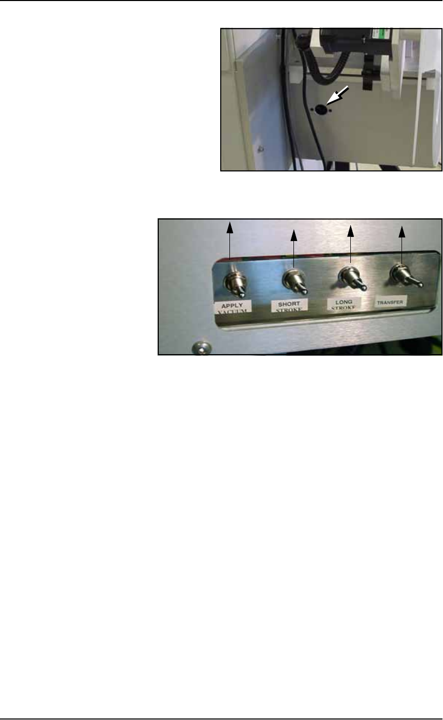
1a. On the PLC Controller:
• Flip the Transfer toggle DOWN
• Flip the Long Stroke toggle DOWN
• Flip the Short Stroke toggle DOWN
Figure 2-23: Toggle switches in DOWN position
1b. On the Tape Output Controller select
6
for Jog. This advances
the carrier tape in 0.04 mm increments.
Continue to press
6
for Jog until the center of the empty pocket
is directly beneath the PNP head.
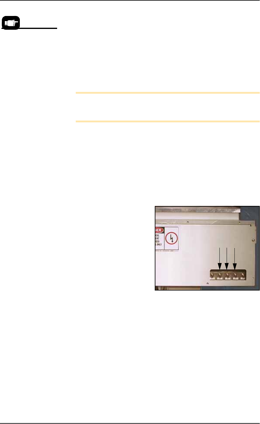
1c. On the PLC Controller, press the black reset button located on its
left side.
Remember, when the
reel is being taped on
the TM-50, the trailer is
the first length of empty
carrier tape run before
the first device is taped,
and the leader is the
length of empty carrier
tape run after the last
device is taped.
■ Setting Up Input and Output Media ◘ Setting Up the Tape Output System
PS Series Owner’s Manual 2—25
back
Figure 2-24: The Reset button on the PLC Controller.
1d. On the front of the controller, flip all toggles UP.
Figure 2-25: Toggle switches should be in UP (normal) position
1e. On the Tape Output Controller, press ESC to enter RUN mode.
The Tape Output System is now ready for programmed devices.
Placing Devices
Devices are placed by the Tape-Out-PNP head when your PS job is
run.
Ending a Taped Run
When all components have been taped or the batch size has been
reached, perform the following:
1. Reset the counter to zero and run out the amount of empty car-
rier tape needed to make the leader.
2. Cut the carrier tape and cover tape.
Replacing a Full Take Up Reel
1. Leave job-specified number of empty pockets on the carrier tape.
2. Cut the carrier tape.
3. Roll carrier tape onto take up reel and remove reel.
4. Install empty take up reel.
5. Continue job.
Setup ■ Setting Up Input and Output Media
2—26 Data I/O • 981-0424-002
back
Set Up for Camera Contrast
If you are programming light colored devices, such as white, silver or
beige, then it may be necessary to flip over the Vision Background
Plate. The Vision Background Plate is located on the Data I/O J-Head
only. One side is white and one side is black. Since most devices are
black, the plate is installed from the factory with the white side down.
To flip the Vision Background Plate over:
1. If the PS Machine power is On, send the head to the Park posi-
tion and then push the E-Stop.
If not, Push the E-Stop and move the head by hand to a location
with easy access.
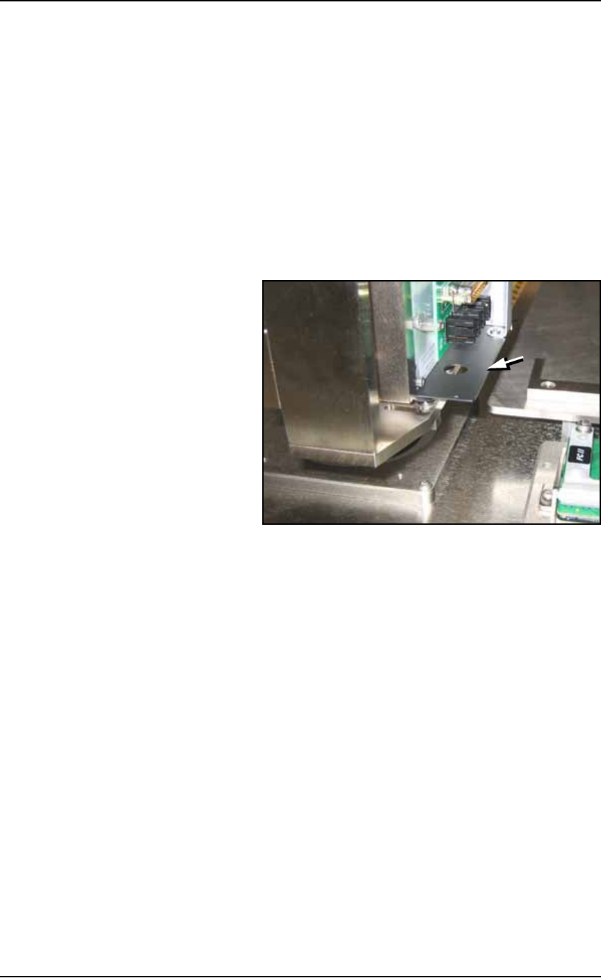
2. Locate the plate at the bottom of the PNP head.
Figure 2-26: The Head Vision Background Plate (arrow) can be
reversed for better vision contrast with light colored devices. This view
is from the back, right side of the J-Head.
3. Remove four SHCS with a 1.5 mm hex key.
4. If the head has a Socket Opener mounted on it:
4a. Turn off the main air supply at the Power Panel.
4b. Pull the Socket Opener down, away from the probe tip.
5. Carefully remove the plate and turn it upside down.
6. Reinstall.
7. Close all Safety Shields, reset the E-Stop, and switch the main air
back on as applicable.