PS288_PS388_PS588_981-0424-002D - 第74页
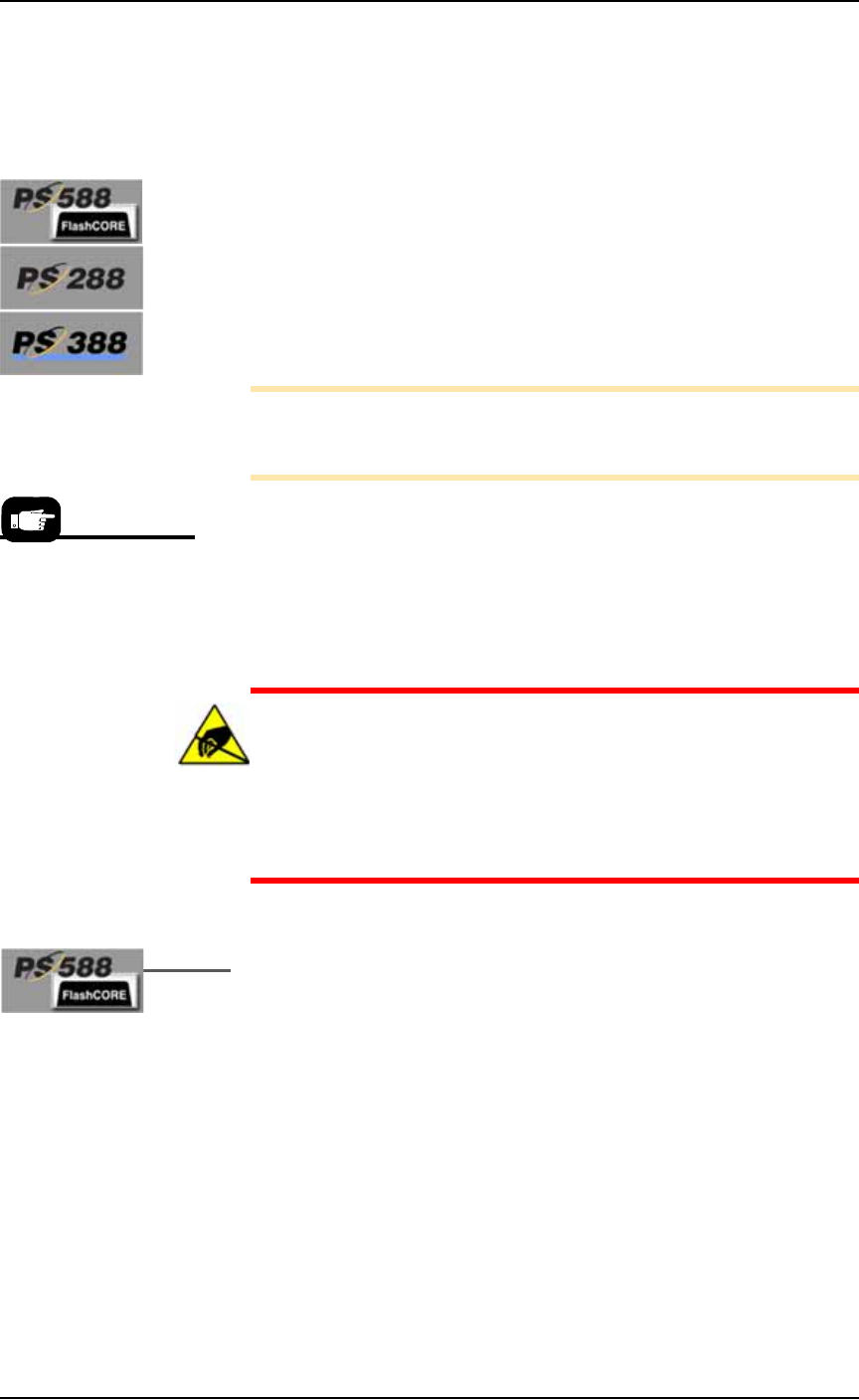
Operation ■ Operator Functions 3—4 Data I/O • 981-0424-002 back Figure 3-3: [PS588 FlashC ORE on ly] Actuator Plat es for Standard Sockets. Align Actuat or Plat e T ype-A notches with the Actuation Bracket notches, and t…
■ Operator Functions ◘ Running a Job on PS Systems
PS Series Owner’s Manual 3—3
back
• The external air line is connected.
• If the air pressure switch is ON, the pressure indicator number is
green.
• If the power is ON, the PNP head is stopped in the Park position.
Installing Socket Adapters – FlashCORE
Socket Adapters can be installed before or after the AH500 Software
has been started. Note that after installing different Socket Adapters,
there are generally three items to adjust: adjusting the socket opener
ribs, adjusting the actuator air pressure, and adjusting the socket
actuator sensors on the air cylinder if necessary.
To install or change a Socket Adapter on a FlashCORE programmer:
Note: To find the correct Socket Adapter part number for your
device/job, 1) Open TaskLink, 2) Select your target job, 3) Click
Edit then Footnotes.
1. If a job is running, click Finish on the Run Window and wait for
the PNP head to empty the sockets, move to the Park position
and stop.
2. Open the safety shield that offers the easiest access to the target
programmer(s).
CAUTION: Electrostatic discharge (ESD) hazard. To prevent
damage to Socket Adapters and devices from ESD, always wear
an antistatic wrist strap.
The wrist strap should be connected to the grounding socket on
the front of the PS Machine and should contain a 1 M-ohm to
10 M-ohm current limiting resistor.
3. [PS588 FlashCORE only] Remove the Actuator Plate—
3a. [Standard sockets only] Type-A (see Figure 3-3): Slide the plate
toward the front of the PS Machine until the notches on the plate
align with the cutouts on the Actuation Bracket. Then lift the
actuator plate up.
Type-B: Slide the plate out toward the front of the PS Machine.
A job can be continued
later even after clicking
Finish.
Operation ■ Operator Functions
3—4 Data I/O • 981-0424-002
back
Figure 3-3: [PS588 FlashCORE only] Actuator Plates for Standard
Sockets. Align Actuator Plate Type-A notches with the Actuation
Bracket notches, and then lift up to remove.
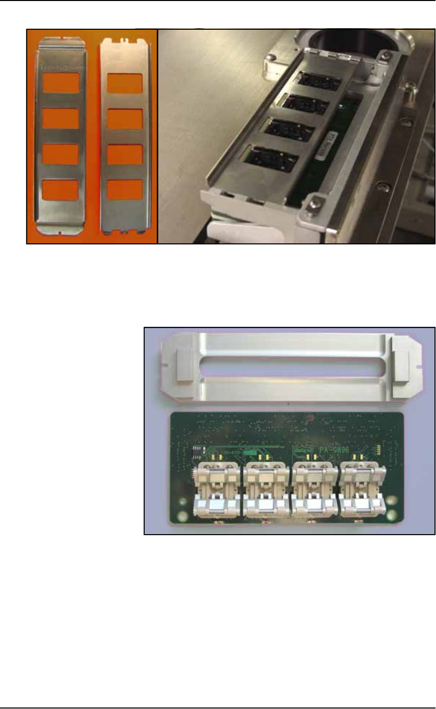
3b. [HIC Adapters only] Slide the plate out toward the front of the
PS Machine. See the figure below.
Figure 3-4: Special Actuation Plate for HIC Adapters.
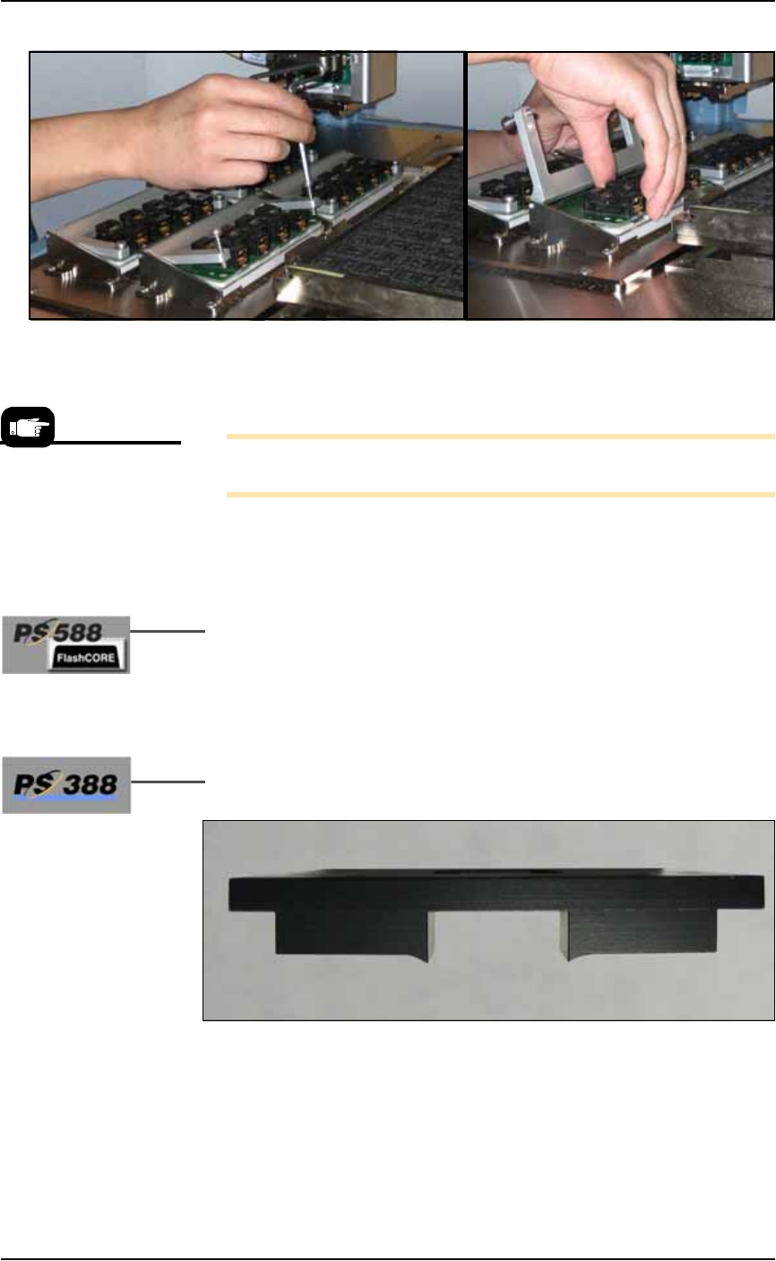
4. Remove the Socket Adapter—
4a. Unscrew the two captive, SHCS with a 4 mm hex key and open
the Adapter Bracket.
Type-B Type-A
■ Operator Functions ◘ Running a Job on PS Systems
PS Series Owner’s Manual 3—5
back
Figure 3-5: Removing the Socket Adapter from the programmer.
(PS388 shown.)
4b. Lift the Socket Adapter up off the dowel pins.
Note: Do not touch the gold contact surfaces on the bottom of the
Socket Adapter.
5. Install the Socket Adapter—
5a. Insert the correct Socket Adapter for your target device, making
sure that it seats on the dowel pins.
5b. Screw in the two screws.
6. [PS588 FlashCORE only] Install the correct Actuator Plate—
6a. Type-A (see Figure 3-3): Install the Actuator Plate by setting it
into the notches on the bracket and sliding back until it snaps
into place.
Type-B: Reinstall the Actuator Plate by placing it into the slot
and sliding it back until it snaps into place.
7. [HIC Socket Adapters only on PS388] Install the correct Socket
Opener for the HIC adapter onto the PNP head.
Figure 3-6: [PS388] Most HIC openers have a radius on the contact
area. Each HIC Socket Adapter may have a its own opener plate.
Matching Socket Adapter part names are on the ends of the opener
plate (not shown here).
Installing the Socket
Adapters and Actuator
Plates can be done later,
after setting media
options in the SETUP Win-
dow.