PS288_PS388_PS588_981-0424-002D - 第76页
Operation ■ Operator Functions 3—6 Data I/O • 981-0424-002 back CAUTION: Collision hazard on PS388. HIC So cket Openers can hit some standard Socket Adapters. Remove standard Socket Adapters from all programmers before u…
■ Operator Functions ◘ Running a Job on PS Systems
PS Series Owner’s Manual 3—5
back
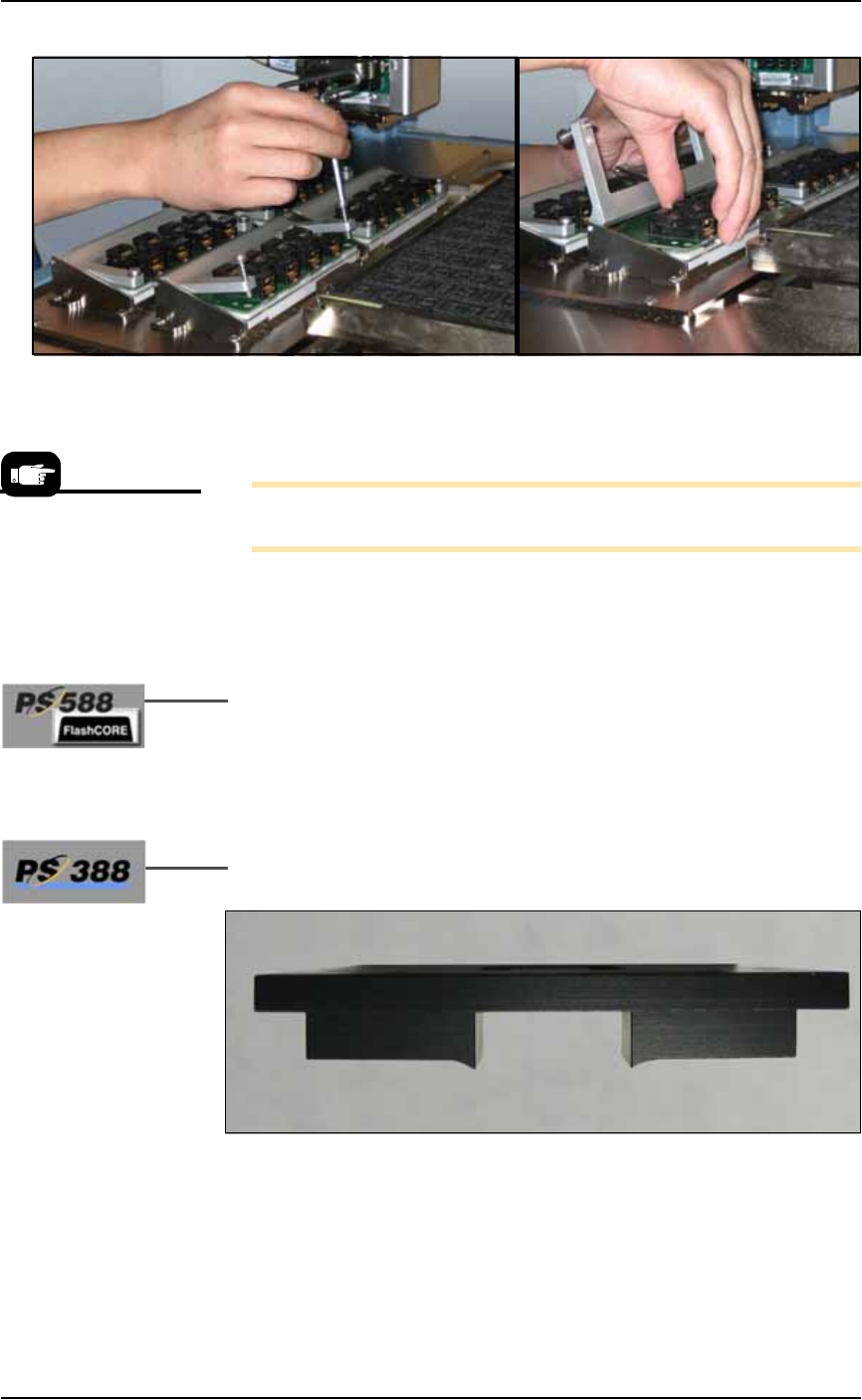
Figure 3-5: Removing the Socket Adapter from the programmer.
(PS388 shown.)
4b. Lift the Socket Adapter up off the dowel pins.
Note: Do not touch the gold contact surfaces on the bottom of the
Socket Adapter.
5. Install the Socket Adapter—
5a. Insert the correct Socket Adapter for your target device, making
sure that it seats on the dowel pins.
5b. Screw in the two screws.
6. [PS588 FlashCORE only] Install the correct Actuator Plate—
6a. Type-A (see Figure 3-3): Install the Actuator Plate by setting it
into the notches on the bracket and sliding back until it snaps
into place.
Type-B: Reinstall the Actuator Plate by placing it into the slot
and sliding it back until it snaps into place.
7. [HIC Socket Adapters only on PS388] Install the correct Socket
Opener for the HIC adapter onto the PNP head.
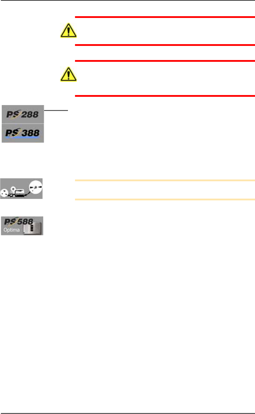
Figure 3-6: [PS388] Most HIC openers have a radius on the contact
area. Each HIC Socket Adapter may have a its own opener plate.
Matching Socket Adapter part names are on the ends of the opener
plate (not shown here).
Installing the Socket
Adapters and Actuator
Plates can be done later,
after setting media
options in the SETUP Win-
dow.
Operation ■ Operator Functions
3—6 Data I/O • 981-0424-002
back
CAUTION: Collision hazard on PS388. HIC Socket Openers can hit
some standard Socket Adapters. Remove standard Socket
Adapters from all programmers before using HIC Openers.
CAUTION: Collision hazard. On PS288 and PS388, the Socket
Opener can possibly hit some Socket Adapters with large clamp-
ing arms such as the G491. After installing a Socket Opener,
always check clearance at all the Socket Adapters.
8. [PS288, PS388] Adjust the Socket Opener Ribs prior to opera-
tion. See Adjust Socket Opener Ribs on page 3-14.
To restart the same job, click Run in the Run Window.
If starting a new job, at the Run Window, click Exit, click Exit again at
the Setup Window, and Exit again to quit the AH500 software. Then in
TaskLink’s Task Manager dialog. select the desired job and click Run.
Follow the on-screen instructions.
Note: If starting a job that uses Tape Output, pull the red
E-Stop/On button on the taping machine to start it.
Installing Socket Adapters – OPTIMA
To change a Socket Adapter on an OPTIMA/Universal Programmer:
Each TOP (Socket Adapter) is connected to Universal programmer
base connectors which are attached to the work surface of the PS588.
1. If a job is running, click Finish on the Run window and wait for
the PNP head to empty the sockets and move to the park posi-
tion.
2. Remove the existing Socket Adapter by holding the sides of the
case and gently rocking and lifting.
■ Operator Functions ◘ Running a Job on PS Systems
PS Series Owner’s Manual 3—7
back
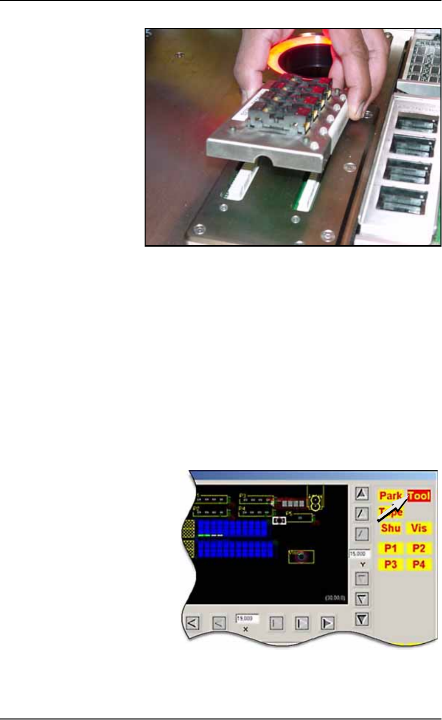
Figure 3-7: Align Socket Adapter and programmer base connectors
3. Holding the new Socket Adapter above the base, align the pins
with the base connector and press down.
4. Adjust the Socket Opener ribs to fit the new sockets. See Adjust
Socket Opener Ribs on page 3-14.
Installing the Correct Probe Tip
Different sized devices require a different size probe tip. Install the
recommended tip onto the probe for your type of PNP head as shown
below.
If the AH500 Software is already started, open the Gantry window
(Start Setup Window > System > Gantry) and click the Tool label to
move the PNP head to a spot where it is accessible. It is okay to move
the probe/opener down in this position without affecting the set
travel height.
Figure 3-8: The Tool position in the Gantry window allow easy access to
the probe tips. The Tool position can also be set by the customer.