PS288_PS388_PS588_981-0424-002D - 第78页
Operation ■ Operator Functions 3—8 Data I/O • 981-0424-002 back Intellepro Head (std on mac hines prior to Ma rch 2009)* - - - - - - - - - - - - - - - - - - - - - - - - - - - - - - - - - - - Data I/O ‘J-Head’ (std on mac…
■ Operator Functions ◘ Running a Job on PS Systems
PS Series Owner’s Manual 3—7
back
Figure 3-7: Align Socket Adapter and programmer base connectors
3. Holding the new Socket Adapter above the base, align the pins
with the base connector and press down.
4. Adjust the Socket Opener ribs to fit the new sockets. See Adjust
Socket Opener Ribs on page 3-14.
Installing the Correct Probe Tip
Different sized devices require a different size probe tip. Install the
recommended tip onto the probe for your type of PNP head as shown
below.
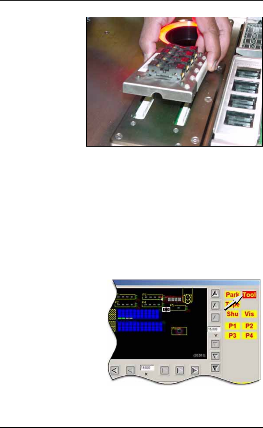
If the AH500 Software is already started, open the Gantry window
(Start Setup Window > System > Gantry) and click the Tool label to
move the PNP head to a spot where it is accessible. It is okay to move
the probe/opener down in this position without affecting the set
travel height.
Figure 3-8: The Tool position in the Gantry window allow easy access to
the probe tips. The Tool position can also be set by the customer.
Operation ■ Operator Functions
3—8 Data I/O • 981-0424-002
back
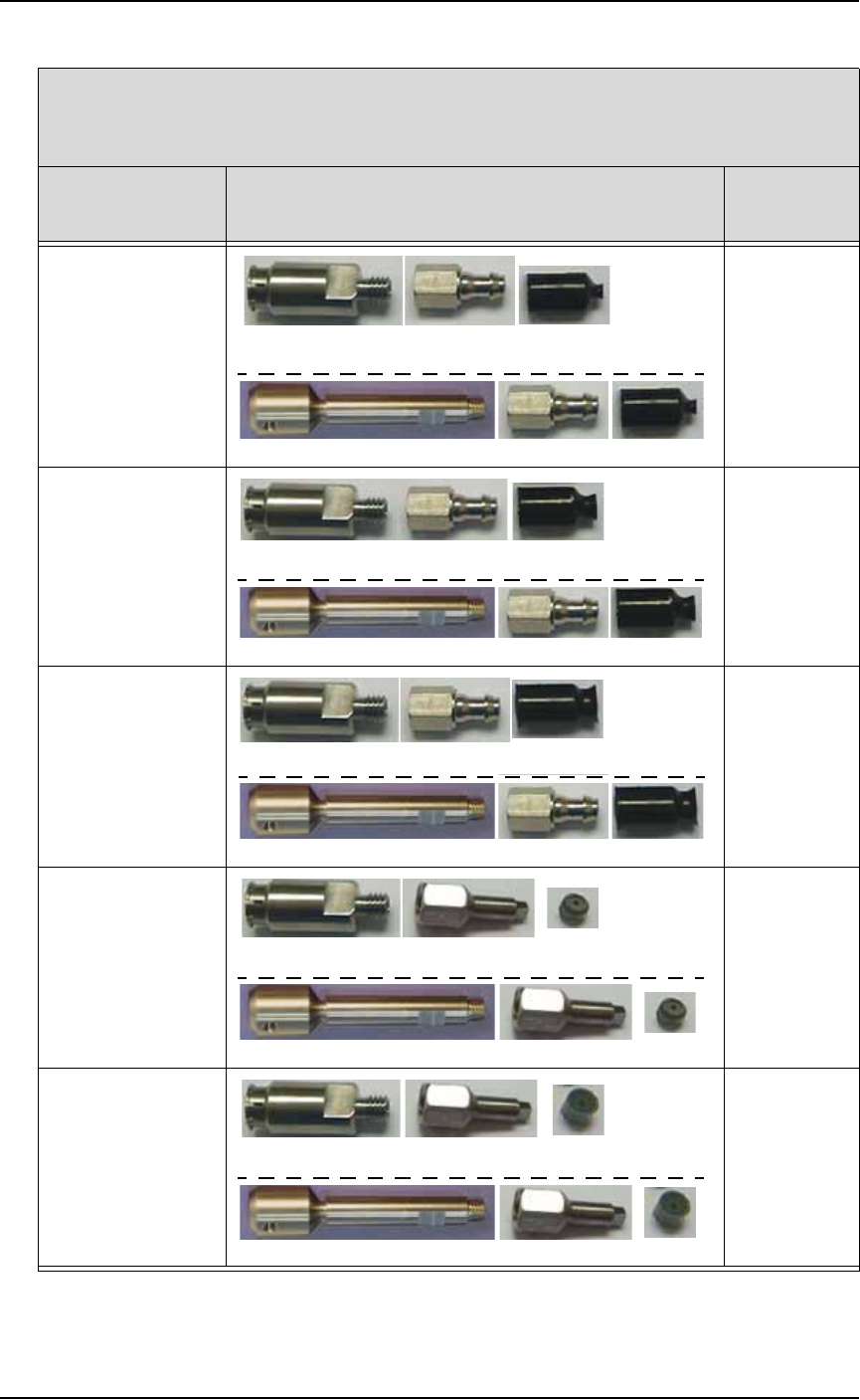
Intellepro Head (std on machines prior to March 2009)*
- - - - - - - - - - - - - - - - - - - - - - - - - - - - - - - - - - -
Data I/O ‘J-Head’ (std on machines March 2009 and later)*
If processing this
device type:
Breakaway Tip (or stem)/ Nozzle/ Cup or Tip
(Data I/O Part Numbers)
probe tip
size
FBGA
μBGA
288-0100-001 288-2500-001 288-0017-001
641-0110-001 288-2500-001 288-0017-001
2 mm cup
300 mil DIP
20 PLCC
32 TSOP
288-0100-001 288-2500-001 288-0018-001
641-0110-001 288-2500-001 288-0018-001
4 mm cup
28 PLCC or greater
40 TSOP or greater
QFP
600 mil DIP
288-0100-001 288-2500-001 288-1000-001
641-0110-001 288-2500-001 288-1000-001
6 mm cup
Small devices such
as QFN20
288-0100-001 638-0007-001 288-0020-001
641-0110-001 638-0007-001 288-0020-001
3.05 mm tip
Small devices such
as QFN40
288-0100-001 638-0007-001 288-0019-001
641-0110-001 638-0007-001 288-0019-001
4.57 mm tip
* What PNP head do I have? See Figure 1-3 on page 1–11.
■ Operator Functions ◘ Running a Job on PS Systems
PS Series Owner’s Manual 3—9
back
The Breakaway Stem on the J-Head
The Breakaway Stem for the Data I/O J-Head has a set screw for
attaching it. It requires a 1.5 mm hex key. Ensure that the O-ring on
the head doesn’t get damaged when installing the stem. The flats on
the stem accept a 5 mm wrench.
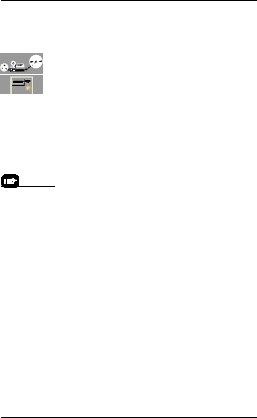
Installing the Correct Shuttle Cups
On systems with Laser Marking or Tape Output, the shuttle cup (and
o-ring) must match the device size for proper suction. Devices with
flat bottoms such as qfp, tsop, and ssop require shuttle cups with
o-ring diameters smaller than the shortest edge of the device. BGA
devices most likely use shuttle cup part numbers 615-0070-001,
615-0063-001 or 615-0067-001. Occasionally, balls on BGA devices will
be on the inside the o-ring and some outside it. Refer to Figure 3-9
below.
To remove and install shuttle cups:
1. Preparation—
1a. Shut off the PS System power and ensure the main power switch
is in the OFF position.
2. Access the shuttles—
2a. Open the nearest safety shield, or remove the laser shuttle cover
as necessary (1/8 inch Hex Key).
3. Replace the shuttles—
3a. Unscrew the two knurled shuttle cups by hand.
3b. Screw in the appropriate sized shuttle cup for your device. See
the chart below.
3c. Replace the laser shuttle cover, if applicable.
Hint: Select a shuttle
cup size that will work
with the largest selec-
tion of your frequent
target devices.