PS288_PS388_PS588_981-0424-002D - 第79页
■ Operator Functions ◘ Running a Job on PS Systems PS Series Owner’s Manual 3—9 back The Breakaway Stem on the J-Head The Breakaw ay Stem for the Data I/O J-Head has a set screw for attaching it. It requires a 1.5 mm hex…
Operation ■ Operator Functions
3—8 Data I/O • 981-0424-002
back
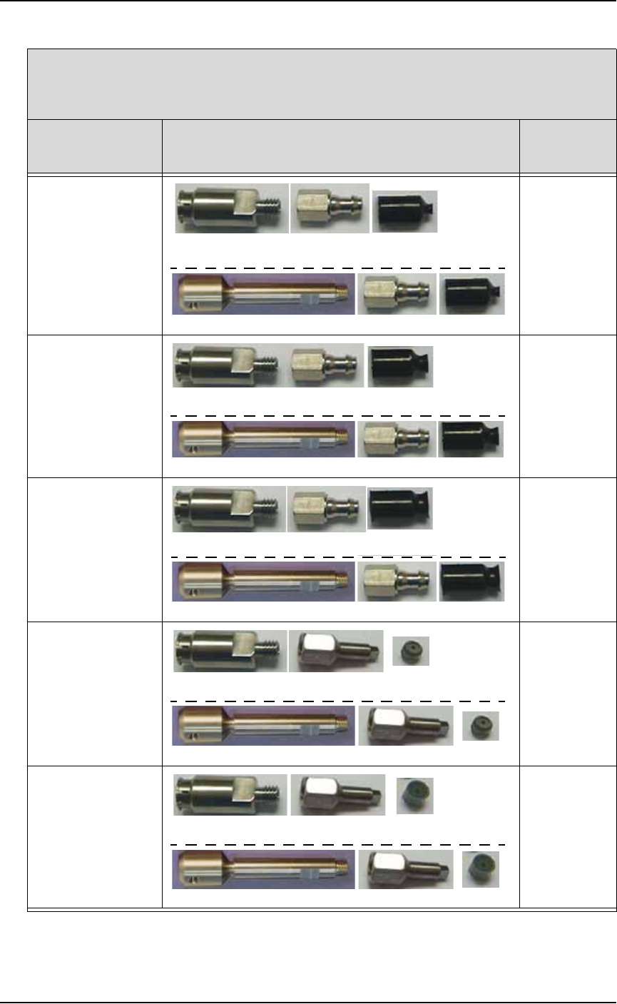
Intellepro Head (std on machines prior to March 2009)*
- - - - - - - - - - - - - - - - - - - - - - - - - - - - - - - - - - -
Data I/O ‘J-Head’ (std on machines March 2009 and later)*
If processing this
device type:
Breakaway Tip (or stem)/ Nozzle/ Cup or Tip
(Data I/O Part Numbers)
probe tip
size
FBGA
μBGA
288-0100-001 288-2500-001 288-0017-001
641-0110-001 288-2500-001 288-0017-001
2 mm cup
300 mil DIP
20 PLCC
32 TSOP
288-0100-001 288-2500-001 288-0018-001
641-0110-001 288-2500-001 288-0018-001
4 mm cup
28 PLCC or greater
40 TSOP or greater
QFP
600 mil DIP
288-0100-001 288-2500-001 288-1000-001
641-0110-001 288-2500-001 288-1000-001
6 mm cup
Small devices such
as QFN20
288-0100-001 638-0007-001 288-0020-001
641-0110-001 638-0007-001 288-0020-001
3.05 mm tip
Small devices such
as QFN40
288-0100-001 638-0007-001 288-0019-001
641-0110-001 638-0007-001 288-0019-001
4.57 mm tip
* What PNP head do I have? See Figure 1-3 on page 1–11.

■ Operator Functions ◘ Running a Job on PS Systems
PS Series Owner’s Manual 3—9
back
The Breakaway Stem on the J-Head
The Breakaway Stem for the Data I/O J-Head has a set screw for
attaching it. It requires a 1.5 mm hex key. Ensure that the O-ring on
the head doesn’t get damaged when installing the stem. The flats on
the stem accept a 5 mm wrench.
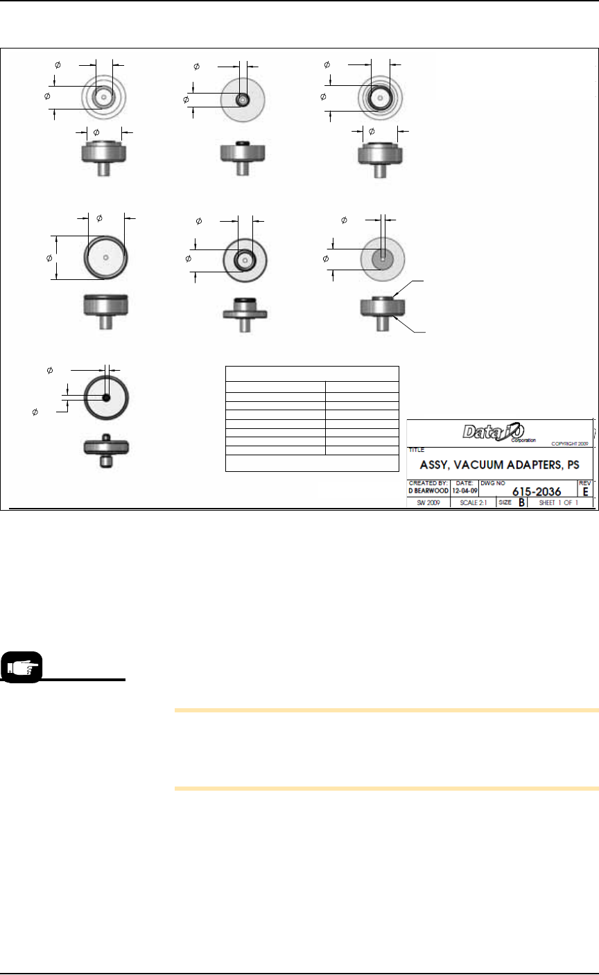
Installing the Correct Shuttle Cups
On systems with Laser Marking or Tape Output, the shuttle cup (and
o-ring) must match the device size for proper suction. Devices with
flat bottoms such as qfp, tsop, and ssop require shuttle cups with
o-ring diameters smaller than the shortest edge of the device. BGA
devices most likely use shuttle cup part numbers 615-0070-001,
615-0063-001 or 615-0067-001. Occasionally, balls on BGA devices will
be on the inside the o-ring and some outside it. Refer to Figure 3-9
below.
To remove and install shuttle cups:
1. Preparation—
1a. Shut off the PS System power and ensure the main power switch
is in the OFF position.
2. Access the shuttles—
2a. Open the nearest safety shield, or remove the laser shuttle cover
as necessary (1/8 inch Hex Key).
3. Replace the shuttles—
3a. Unscrew the two knurled shuttle cups by hand.
3b. Screw in the appropriate sized shuttle cup for your device. See
the chart below.
3c. Replace the laser shuttle cover, if applicable.
Hint: Select a shuttle
cup size that will work
with the largest selec-
tion of your frequent
target devices.
Operation ■ Operator Functions
3—10 Data I/O • 981-0424-002
back
Figure 3-9: O-ring ID and OD dimensions and Part Numbers are shown.
Turning System Power On
Before you turn on power, check that:
• All safety shields are closed.
• The external air line is connected, the air pressure switch is in
the ON position, and the pressure indicator number is green.
Turn the power on at the back of the machine by rotating the large
switch to the ON position.
Note: Turning power on does not start the PS Application Soft-
ware (AH500). Although the AH500 icon on the monitor can be
double-clicked, the best way to start the application is by first start-
ing TaskLink. See the heading below.
Starting AH500 via TaskLink (Selecting a Job)
TaskLink automatically starts AH500 Application Software when
Run is clicked. TaskLink is Data I/O’s software for creating program-
ming jobs by guiding customers through selection of data file, and
programming parameters and processes.
.419
.559
.774
TITLE
OR IN PART, NOR DISCLOSED TO OTHERS WITHOUT
DO NOT SCALE DRAWING.
DIMENSIONS IN INCHES.
IN ACCORDANCE WITH ANSI Y14.5M-1994.
DATE:
D BEARWOOD
CREATED BY:
ASSY, VACUUM
THIS DOCUMENT CONTAINS INFORMATION CONSIDERED
INTERPRET DIMENSIONS & TOLERANCES
DW
SCALE 2:1
SHEET METAL TOLERANCES:
PROPRIETARY A ND SHALL NOT BE REPRODUCED WHOLLY
SPECIFIC WRITTEN PERMISSION OF DA TA I/O CORP
SW 2009
HOLE TO HOLE = .005
EDGE TO HOLE =
.01
EDGE TO EDGE =
.01
FOLD TO HOLE =
.01
FOLD TO FOLD =
.02
HOLE SIZE =
.004
ANGLES =
1.5
12-04-09
1.
615-0071-001
615-0066-001 615-0067-001
615-0068-001
615-0069-001
615-0070-001
615-0063-001
TWO REQUIRED FOR EACH
NO TES:
DESCRIPTIONREV.
REVISIONS
E INITIAL RELEASE OF VACUUM ADAPTER KIT
TOP REPLACEMENT SEALS
VAC ADAPTER ASSY # TOP SEAL #
615-0063-001 249-0020-001
615-0066-001 249-0005-001
615-0067-001 249-0012-001
615-0068-001 249-0004-001
615-0069-001 249-0003-001
615-0070-001 249-0007-001
615-0071-001 288-0020-001
BOTTOM REPLACEMENT SEAL # 249-0003-001
LOWER SEAL TYP.
TOP SEAL TYP.
.470
.085
.175
.309
.120
.089
.774
.507
.381
.335
.491
.977
.799
TRANSFER SHUTTLE SYSTEM
On machines prior to
March 2009, after
machine power-up,
push the green ON but-
ton on the AutoPak.