PS288_PS388_PS588_981-0424-002D - 第85页
■ Operator Functions ◘ Running a Job on PS Systems PS Series Owner’s Manual 3—15 back Figure 3-1 7 : Main air valv e on the back of the machine. 1b. By hand, adjust the Socket Opene r so that the ribs open the socket as …
Operation ■ Operator Functions
3—14 Data I/O • 981-0424-002
back
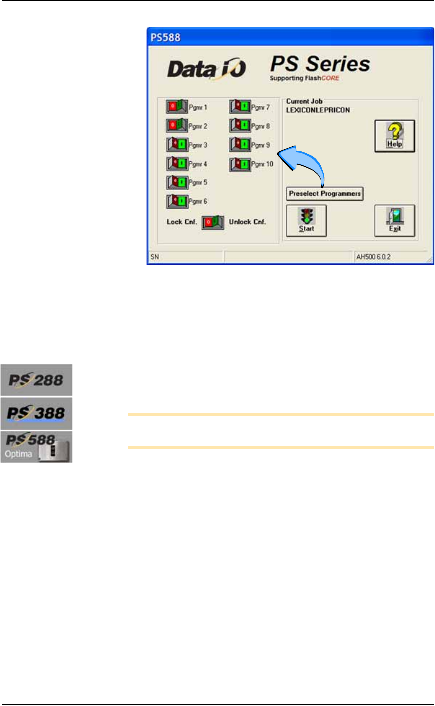
Figure 3-16: Preselecting programmers. In this image, programmers 1
and 2, are disabled. (PS588 shown.)
4. Lock the configuration again only if you wish to keep this setting
the next time the system is turned on: click the O (red) side of the
Lock Cnf button
Adjust Socket Opener Ribs
[PS288, PS388, and Optima on PS588 only]
1. Adjust the Socket Opener Ribs—
Note: It is necessary to adjust the Socket Opener after installing
different Socket Adapters.
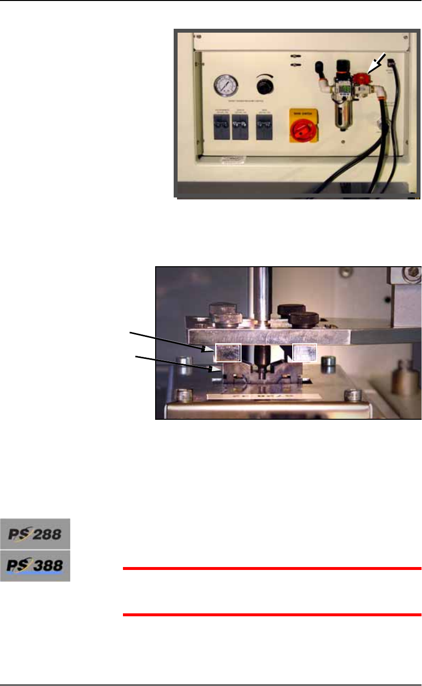
1a. On the Power Panel, turn the main air valve OFF. (It is off when
the lock rings line up: some models.)
■ Operator Functions ◘ Running a Job on PS Systems
PS Series Owner’s Manual 3—15
back
Figure 3-17: Main air valve on the back of the machine.
1b. By hand, adjust the Socket Opener so that the ribs open the
socket as the probe descends and so the opener does not inter-
fere with the device as it is picked up by the probe.
Figure 3-18: Adjusting the Socket Opener on PS288 and PS588
Optima. (Optima programmer shown.)
1c. On the Power Panel, turn the main air valve ON.
Adjust Two Items After Changing Socket Adapters
Adjust the Socket Actuatro Air Pressure
[PS288 & PS388 only when switching between special Socket
Adapters]
CAUTION: Possible damage to Socket Adapters. If the actuation
air pressure is incorrect, Socket Adapters might get damaged, or
throughput could suffer.
Ribs
Socket

Operation ■ Operator Functions
3—16 Data I/O • 981-0424-002
back
If you run a job witch requires a change between a HIC Socket
Adapter and a Standard Socket Adapter, or vise-versa, then THE
ACTUATOR AIR PRESSURE MUST BE CHANGED. See Adjusting
the Socket Actuator Air Pressure on page 4-8.
Adjust the Socket Actuator Sensors
[PS288, PS388 and Optima Programmers only on PS588]
Check the stroke to ensure the socket is opening and closing com-
pletely. If not see Adjusting the Socket Actuator Sensors on page 4-5.
Set Media and Options—the Setup Window
1. Configuring—
1a. On the AH500-PS System main window, click Start.
1b. On the Options tab of the Setup Window, select the desired Input,
Output, and Reject media. Refer to Figure 3-20.
1c. If marking is On, and vision is On, and you need better place-
ment accuracy, check the box Moving To Shuttle: the probe will go
to the camera before going to the shuttle. See upper left corner of
Figure 3-19.
1d. [Tube Input/Output only] Optional: When the box 1st + last
2/tube item is checked, the Vision System checks only the first
and last devices in a Tube. Use this with the Vision System toggle
Off.
If you want the Vision System to check every device, set Vision
System to ON (and uncheck 1st + last 2/tube.) Refer to the fig-
ure below.
For all of step 1, refer
to Figure 3-20 on page
3–18.