PS288_PS388_PS588_981-0424-002D - 第87页
■ Operator Functions ◘ Running a Job on PS Systems PS Series Owner’s Manual 3—17 back Figure 3-19: T ube Input and Output are select ed here. (Vibrat or input/output are T ubes.) Common setups will not display al l the o…

Operation ■ Operator Functions
3—16 Data I/O • 981-0424-002
back
If you run a job witch requires a change between a HIC Socket
Adapter and a Standard Socket Adapter, or vise-versa, then THE
ACTUATOR AIR PRESSURE MUST BE CHANGED. See Adjusting
the Socket Actuator Air Pressure on page 4-8.
Adjust the Socket Actuator Sensors
[PS288, PS388 and Optima Programmers only on PS588]
Check the stroke to ensure the socket is opening and closing com-
pletely. If not see Adjusting the Socket Actuator Sensors on page 4-5.
Set Media and Options—the Setup Window
1. Configuring—
1a. On the AH500-PS System main window, click Start.
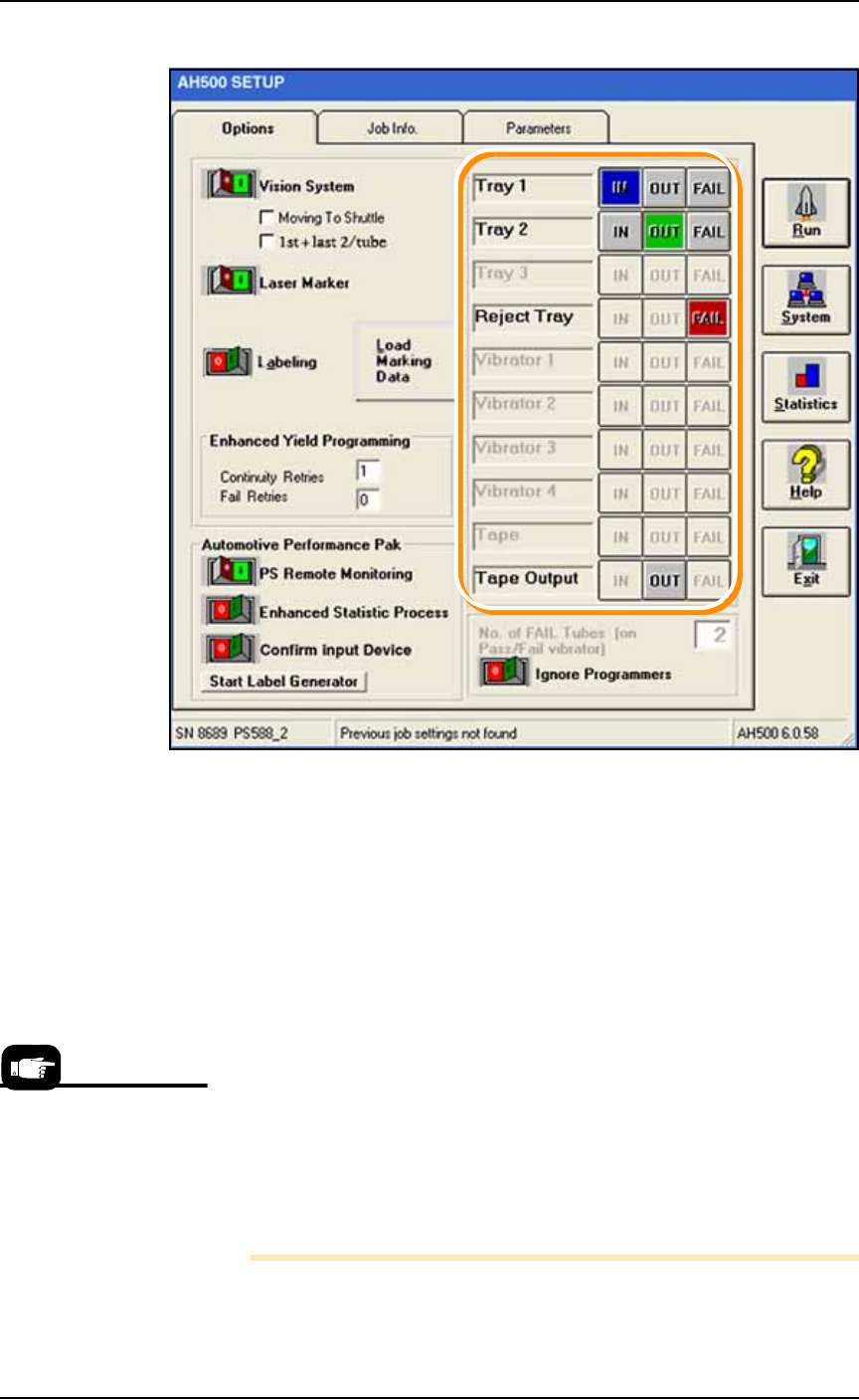
1b. On the Options tab of the Setup Window, select the desired Input,
Output, and Reject media. Refer to Figure 3-20.
1c. If marking is On, and vision is On, and you need better place-
ment accuracy, check the box Moving To Shuttle: the probe will go
to the camera before going to the shuttle. See upper left corner of
Figure 3-19.
1d. [Tube Input/Output only] Optional: When the box 1st + last
2/tube item is checked, the Vision System checks only the first
and last devices in a Tube. Use this with the Vision System toggle
Off.
If you want the Vision System to check every device, set Vision
System to ON (and uncheck 1st + last 2/tube.) Refer to the fig-
ure below.
For all of step 1, refer
to Figure 3-20 on page
3–18.
■ Operator Functions ◘ Running a Job on PS Systems
PS Series Owner’s Manual 3—17
back
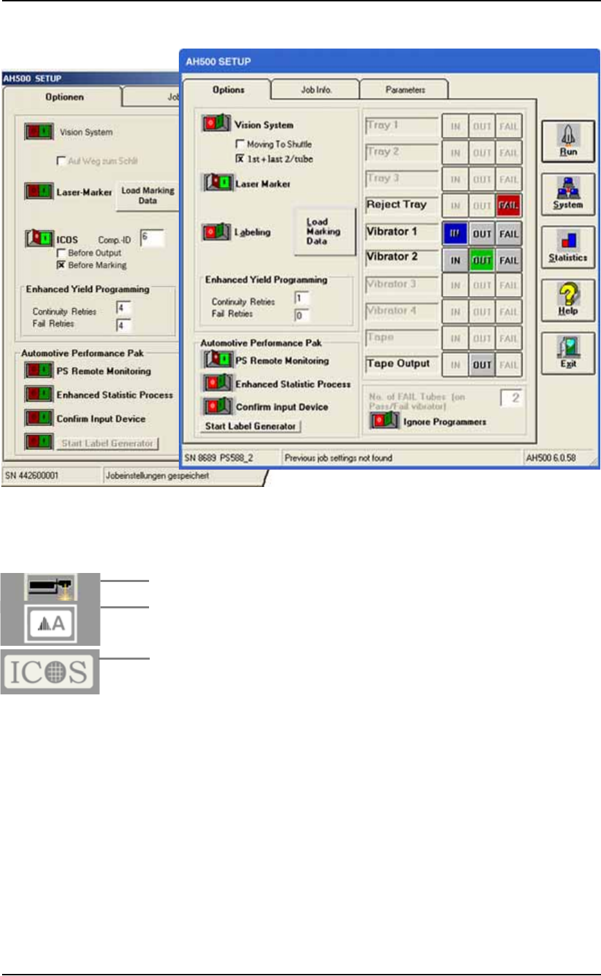
Figure 3-19: Tube Input and Output are selected here. (Vibrator
input/output are Tubes.) Common setups will not display all the
optional features shown here. The left image shows the ICOS
inspection System settings.
1e. [Laser Marking System only] Turn the Laser Marker On (green)
or Off (red).
1f. [Label Marking only] Turn the Labeling toggle On (green) or Off
(red).
1g. [If the ICOS Inspection System is installed] the settings will
appear as shown in the image on the left side of Figure 3-19
above. It can be turned On or Off with the toggle switch. The
Comp-ID number defines the inspection job and is read from the
PS System Package file. The two check boxes below it allow
selecting when to inspect the devices. Both can be selected.
Operation ■ Operator Functions
3—18 Data I/O • 981-0424-002
back
Figure 3-20: The SETUP Window requires input, output, and reject
selections (boxed here) on the Options tab. Only options set in the
WinAH400.ini file will display. Common setups will not display all the
optional features shown here.
Enhanced Yield Programming
1h. (Optional) In the Continuity Retries field, enter the number of
times the system should retry continuity failures before rejecting
the device.
1i. (Optional) In the Fail Retries field, enter the number of times the
system should retry programming failures (excluding over-cur-
rent and continuity) before rejecting the device.
1j. [Automotive Performance Pak only] Optional: Start any of the
five utilities available with the AP Pak.
1k. If Ignore Programmers is On (green), the PNP head will not stop
at the programmers and will effectively transfer devices from
input media to output media with no programming, and with or
without laser marking. The default is Off.
Note: Only installed options are available for selection on the
Options tab. If different input media (tube, tape, or tray) is desired,
For more information on
the AP Pak, see the AH500
online Help.