PS288_PS388_PS588_981-0424-002D - 第91页
■ Operator Functions ◘ Running a Job on PS Systems PS Series Owner’s Manual 3—21 back 1b. Install the correct probe tip for y our device if it has not yet bee n installed. See Installing the Correct Probe T i p on page 3…
Operation ■ Operator Functions
3—20 Data I/O • 981-0424-002
back
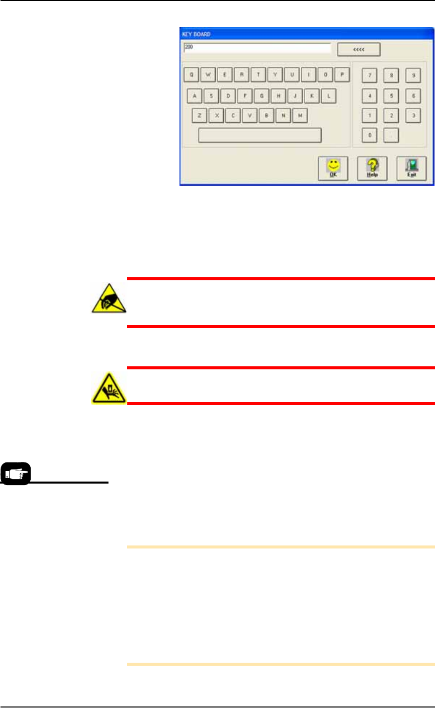
Figure 3-22: The Keyboard dialog opens after clicking in the Pass Limit
field. The <<<< button erases the right-most digit. Exit cancels any
changes.
Install Media and Options—the Workspace
CAUTION: Electrostatic discharge (ESD) hazard. Wear an ESD
strap or discharge static against a common ground to prevent
damage to Socket Adapters and devices.
CAUTION: Safety hazard. Always make sure that the PNP head
is stopped in the Park position before opening any access doors.
Regardless of input media used (trays, tape, or tubes), all devices
should be installed right-side-up (live bug orientation), with the
device leads pointing down and identifying marks visible on the top
of the device.
1. Install hardware—
1a. If Socket Adapters have not yet been installed for the job on all
programmers to be used, do it now. See Installing Socket Adapters
– FlashCORE on page 3-3 or Installing Socket Adapters – OPTIMA
on page 3-6.
Note: If you have already started AH500 and do not know the cor-
rect Socket Adapter Part Number for your device, you can find it
two ways without having to exit AH500: A— On our Web site: 1)
Click Support > Device > Search for Support, 2) Type your device
PN into Device PN field, 3) Click Begin Search for Devices. See
the PNs in the right, results column; and method B— If you
already have a Vision or Package file and you’ve named it after the
Socket Adapter, see the last two fields of the Setup > Job Info Win-
dow (refer Figure 3-21).
For instructions on how to
set up input/output Media,
see:
• Static Tray, page 2-7
• Automatic Tray Feeder,
page 2-10
• Tube, page 2-12
• Tape Input, page 2-16
• Tape Output, page 2-19.
■ Operator Functions ◘ Running a Job on PS Systems
PS Series Owner’s Manual 3—21
back
1b. Install the correct probe tip for your device if it has not yet been
installed. See Installing the Correct Probe Tip on page 3-7.
1c. Install input and output media. (For more, see Chapter 2.) Pin 1
on most Data I/O Socket Adapters is away from the operator
(toward the back of the machine.)
CAUTION: Possible socket and device damage. If the incorrect
Package file was selected during Task creation, or if device rota-
tion was taught incorrectly, devices or socket contacts may get
damaged. If you have any doubts about the Package file, con-
tact your system administrator.
1d. (Optional) Install marking or labeling options as desired. (For
more, see Chapter 2.)
2. (Optional) Set up for Sort-On-Error-Code—
2a. Install a second Reject Bin 50 mm (2 inches) to the right of
Reject 1.
Start Programming
After setting up the machine hardware, input/output media and
options, the job is ready to be run.
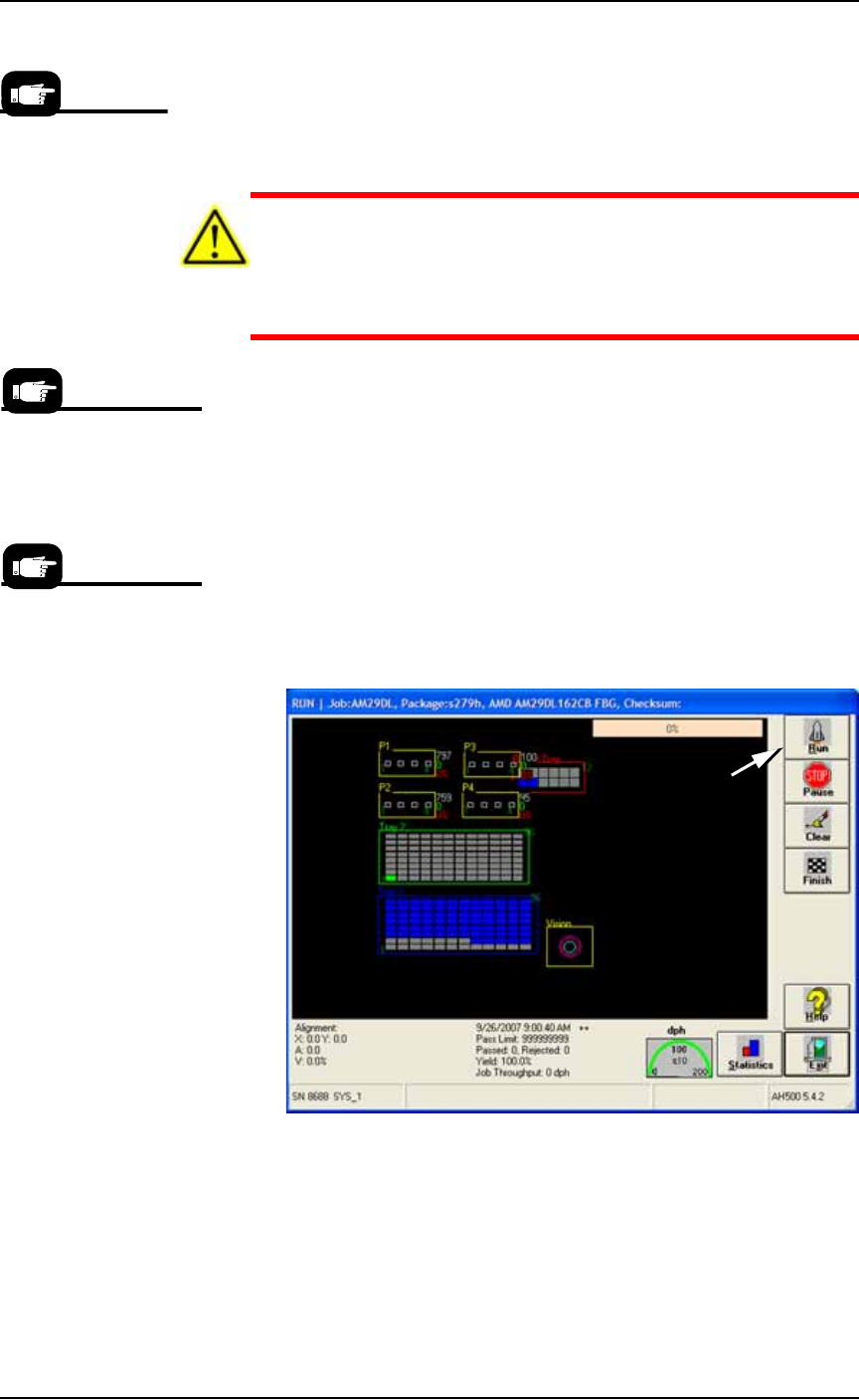
1. At the Setup Window, click Run.
2. On the Run Window, click Run.
Figure 3-23: Run on the Run Window starts programming. (PS288
shown.)
3. A message appears announcing that Tray 1, Tray 2, and Fail Tray
have been found. Click OK.
The PNP head begins its movements. The Run Window tracks
head movement (white square), and displays device placement.
Socket status indicators appear inside the programmer outlines.
Your system adminis-
trator generally has
information on pin 1
orientation for tray
and tape input as
defined by your facil-
ity.
For setting
Sort-On-Error-Code in the
winAH400.ini file, see the
on-screen Help.
If a different device type
is to be programmed, a
different job must be
selected in TaskLink.
Operation ■ Operator Functions
3—22 Data I/O • 981-0424-002
back
Note: If the input/output media are tubes, tube vibration might
need adjustment if devices do not move easily. Use the vibration
controls on the front of the PS System to adjust tube vibration.
Stopping the System
There are three methods for stopping the PS System:
• Emergency Stop— Stop the movement of the head immediately.
• Pause a Job— Pause a job to stop the head at its next destination.
Devices finish programming if started but are not removed from
sockets. The programming session can be continued.
• Finish a Job— Stop picking blank devices, finish the current
programming cycle, and remove devices from all the sockets
placing them into appropriate media. The programming job can
be resumed.
Emergency Stop
To prevent bodily injury or damage to equipment in an emergency,
press the red Emergency Stop (E-Stop) button located on the upper
sides of the machine. Pressing an E-Stop button immediately stops
motion of the PNP head and the gantry.
WARNING: Electric shock and collision hazards. In an emergency,
do not use the on-screen Pause button to turn off power. PRESS-
ING PAUSE DOES NOT REMOVE POWER to the system. In an
emergency, press the Emergency-Stop button.
The Pause button has an
image of a stop sign on
it (red octagon).