Printer 710-810 v9 Blue Under Screen Cleaner Module - 第4页
BLUE UNDER SCREEN CLEANER MODULE OVERVIEW 24.4 Technical Reference Manual C hapter Issue 1 0, Jul 16 VF10 V acuum Filtration Unit The onboard VF10 V enturi V acuum Filtration Unit, located in the front of the machine fra…
BLUE UNDER SCREEN CLEANER MODULE
OVERVIEW
Chapter Issue 10, Jul 16 Technical Reference Manual 24.3
Vacuum Filtration The vacuum filtration unit extracts solvent fumes and draws excess print
material onto the paper.
Vacuum filtration is optional and may be one of the following types:
• VF35i Vacuum Filtration Unit
• VF25 Vacuum Filtration Unit
• VF10 Venturi Vacuum Filtration Unit
NOTE
For information on the removal and replacement of the filters, refer to the
Preventive Maintenance manual.
Figure 24-2 Vacuum Option
VF35i Vacuum
Filtration Unit
The onboard VF35i vacuum filtration unit is protected by two circuit breakers on
the front panel of the base unit. A 15A (for 115V) and an 8A (for 230V) which
can be reset by pressing the circuit breaker button covered by a clear plastic
protector. For safety, the voltage selector control knob is removed from the
switch and bolted to the fan housing. The VF35i vacuum filtration unit has a
three position mechanical air flow adjuster to regulate the air flow as follows:
• Maximum (full air flow)
• Medium (half air flow approximately)
• Minimum (15% of full air flow approximately)
VF25 Vacuum
Filtration Unit
The onboard VF25 vacuum filtration unit is protected by either a 10A (for 115V
units) or 5A (for 230V units) circuit breaker.
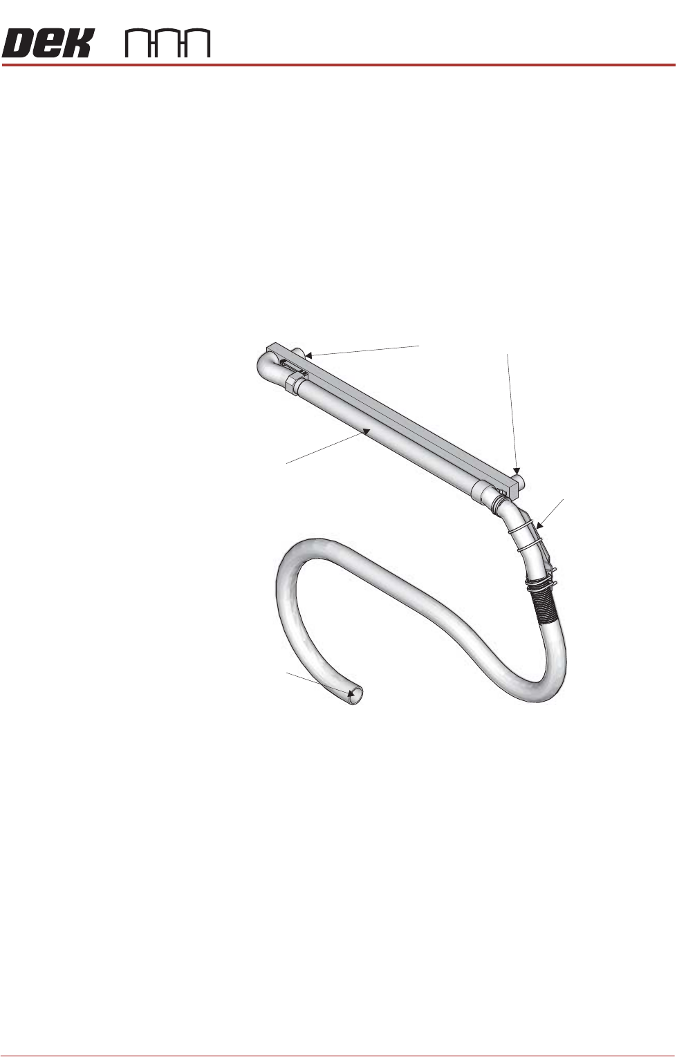
Screen Cleaner Connection
Vacuum Connection
Telescopic Tube
Machine Mount

BLUE UNDER SCREEN CLEANER MODULE
OVERVIEW
24.4 Technical Reference Manual Chapter Issue 10, Jul 16
VF10 Vacuum
Filtration Unit
The onboard VF10 Venturi Vacuum Filtration Unit, located in the front of the
machine frame, uses compressed air to create a vacuum.
BLUE UNDER SCREEN CLEANER MODULE
ELECTRICAL SCHEMATIC
Chapter Issue 10, Jul 16 Technical Reference Manual 24.5
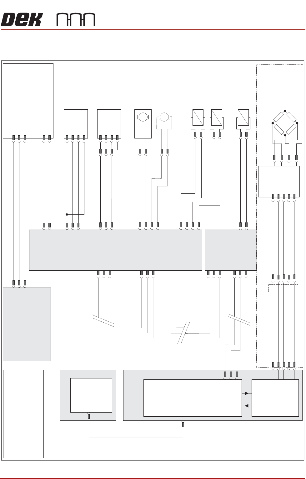
ELECTRICAL SCHEMATIC
Figure 24-3 USC with VF25, V30 or VF35 Vacuum Filtration Unit
M36 Machine
Control Enclosure
PC
Motherboar
d
USB
NextMove ES
(I/O Node 1)
1
2
4
CAN_H
CAN_L
CAN GND
M36PL35
16SK08
Cleaner
Squeegee Bar
16SOL08
DIG OU
T
14
0V
I/Ps
CAN Bus
O/Ps
9SK63
1
4
3
6
7
9PL64
Solvent
Load Cell
9SE26
NextMove
Interface
M36PL09
Solvent ‘Time To Go’(TTG) Option
1
2
10
12
14
8
7
5
1
AN IN0 -
AN IN0 +
0V USR
+12V
-12V
M37 Power Supply Module
Solvent
LevelAmp
-V
+V
-IN
+IN
Vacuum Filtration Unit
NOTE
For Vacuum sensing
Option refer to circuit
185229.
L
N
E
Vac
Pump
Supply
Main Machine
I/O Node 2
N2SK2
CAN In
N2PL4
7
2
3
9
21
L
N
E
M37PL35
M35SK02
M35SK01
1
2
Screen Clean
I/O Node 4
N2SK3
7
2
3
9PL69
1
4
3
6
7
Level+
Ext Service Panel
AGND
0V USR
+12V
-12V
CAN Out
N4SK3
7
2
3
CAN Out
N4SK2
7
2
3
CAN In
1
2
N4PL6
8SK13
R/H Clean
Home Clamp
8SOL20
N4PL2
DIG OU
T
0
0V
1
2
3
4
1
2
8SK11
L/H Clean
Home Clamp
8SOL19
1
2
DIG OU
T
0
0V
N4PL5
1
2
3
4
DIG OU
T
3
0V
+12V
Sig
0V
(L)
N4PL4
4
5
6
Screen
Cleaner
Home
8SE10
DIG IN 2
DIG OU
T
1
8SK76
8SK71
1
2
N4PL1
4
5
6
DIG IN 1
Paper Low/
Paper Usage
8SE18
Solvent
Pump
8M14
0V
24V
M
M
Paper Feed
Motor
8M5
8SK72
1
2
DIG OU
T
2
0V
+12V
Sig
0V
(L)
N/
C
NOTE
The breaks in the CAN Bus chain
reflect that additional I/O Nodes
may be fitted, refer to Machine
Control chapter for the complete
CAN Bus chain.