00198532-01_SM_MeasurementFeeder_EN.pdf - 第14页
2 Replacing spare parts 2.4 Side cover left 14 Service Manual SIPLACE MeasurementFeeder X 02/2020 2.4 Side cover left NOTICE Avoiding damaging the board To avoid damaging the threaded bolts on the printed circuit board, …
2 Replacing spare parts
2.3 Rear sliding Guide
Service Manual SIPLACE MeasurementFeeder X 02/2020 13
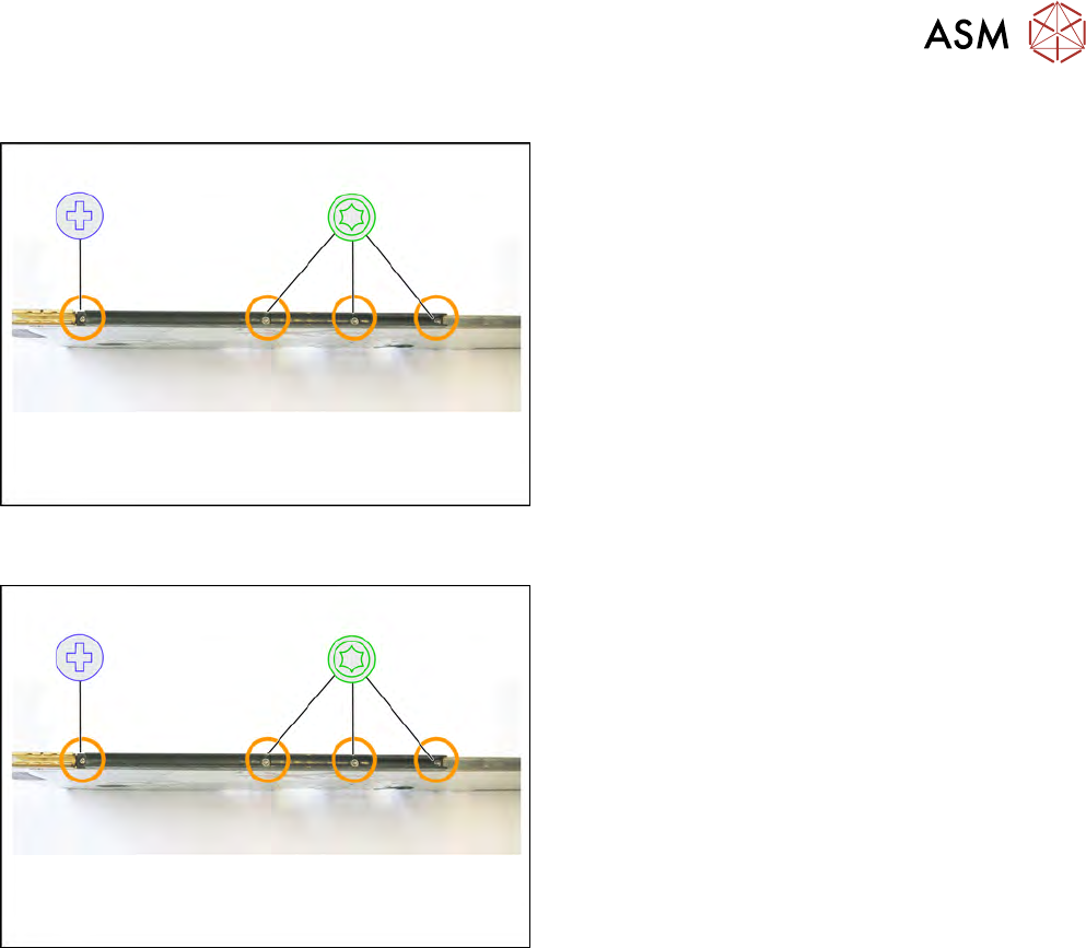
2.3.1 Removing the Sliding Guide
► Turn the feeder module so that its underside is at
the top.
► Remove the Phillips screw from the left side.
► Remove the three TORX screws from the right
side.
► Lift the gliding slide upwards and off.
2.3.2 Fitting the Sliding Guide
► Turn the feeder module so that its underside is at
the top.
► Fit the guiding slide – as illustrated – to the un-
derside of the feeder module.
Observe the arrangement of the drilled holes in
the guiding slide.
► Push the guiding slide, as shown, to the left
(front) towards the front guiding slide, as far as
the stop.
► Now lower the two snap tabs of the guiding slide
into the openings provided on the underside of
the feeder module.
► Fasten the sliding guide on the left side to the
feeder module, using the Phillips screw "ISO
7045 - M2.5 x 6-A2-50-H" tightened to 0.6N.
► Use the 3 TORX screws to fix the guiding slide
on the right side with 0.6Nm to the feeder mod-
ule.
2 Replacing spare parts
2.4 Side cover left
14 Service Manual SIPLACE MeasurementFeeder X 02/2020
2.4 Side cover left
NOTICE
Avoiding damaging the board
To avoid damaging the threaded bolts on the printed circuit board, only remove the side
cover if the other side cover has been fully fitted i.e. with all screws.
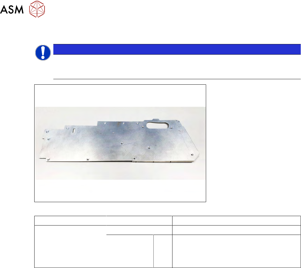
Fig.3: Side cover left
Feeder module Item no. Designation
MeasurementFeederX 03153782-xx Side cover left
03010209-xx
03033796-xx
03045178-xx
A
B
C
Screws:
7045 M2.5X6 (Phillips screw)
SN 2.5X6 (TORX screw)
ISO7380 M2X2.5 (Allen screw)
Required tools
●
Phillips screwdriver 0.9 Nm
●
TORX screwdriver 0.6 Nm, size T8
●
Allen key, size M2
2 Replacing spare parts
2.4 Side cover left
Service Manual SIPLACE MeasurementFeeder X 02/2020 15
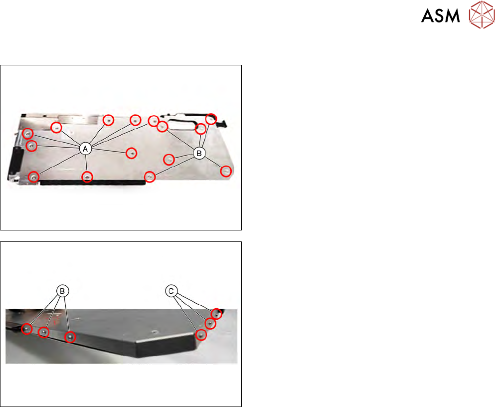
2.4.1 Removing the side cover
► Carefully place the feeder module with the right
side down on a stable, level and clean surface.
► Loosen the screws as shown in the diagram.
For the screws marked with A you need a Phillips
screwdriver.
For the screws marked with B you need a TORX
screwdriver.
► Pull the side cover down and out.
► Loosen the screws as shown in the diagram.
For the screws marked with B you need a TORX
screwdriver.
For the screws marked with C you need an Allen key.
► Remove the side cover.