00198532-01_SM_MeasurementFeeder_EN.pdf - 第20页
2 Replacing spare parts 2.6 Contact module 20 Service Manual SIPLACE MeasurementFeeder X 02/2020 Notice During insertion, make sure that the two pressure springs point forwards to the EDIF and are not distor- ted. ► Push…
2 Replacing spare parts
2.5 EDIF
Service Manual SIPLACE MeasurementFeeder X 02/2020 19
2.5.2 Fitting the EDIF
CAUTION
Damaging the EDIF connector
The EDIF connector is very sensitive to high torques. During assembly, always observe the
torque specifications, otherwise the EDIF connector could be damaged!
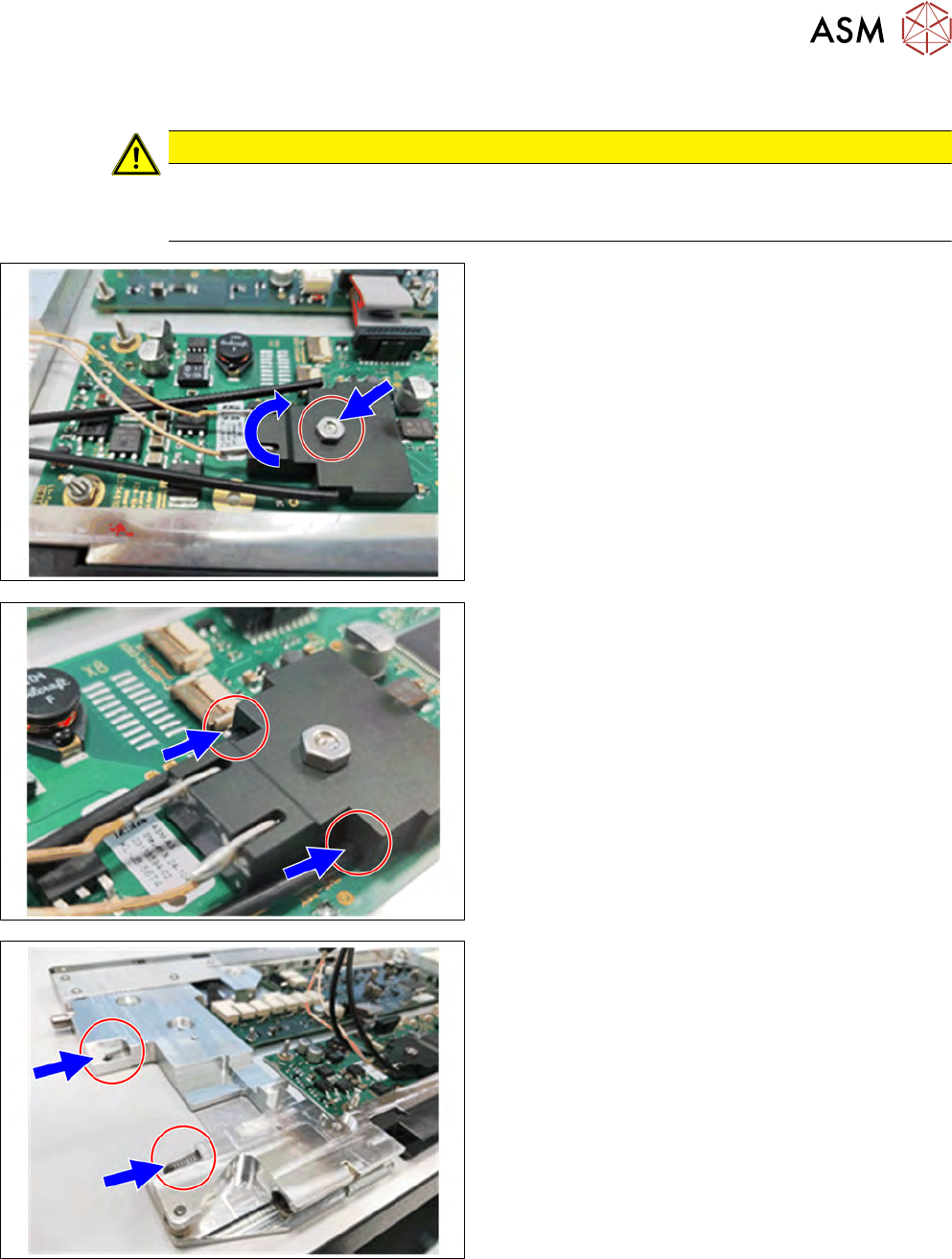
► Plug the EDIF connector onto the control board.
► Tighten the nut.
► Insert the two fiber optics into the EDIF con-
nector.
► Insert the two pressure springs into the ducts
provided.
If the pressure springs are bent, these will need to be
replaced.
2 Replacing spare parts
2.6 Contact module
20 Service Manual SIPLACE MeasurementFeeder X 02/2020
Notice
During insertion, make sure that the two pressure
springs point forwards to the EDIF and are not distor-
ted.
► Push the EDIF into the recess at the front of the
feeder module.
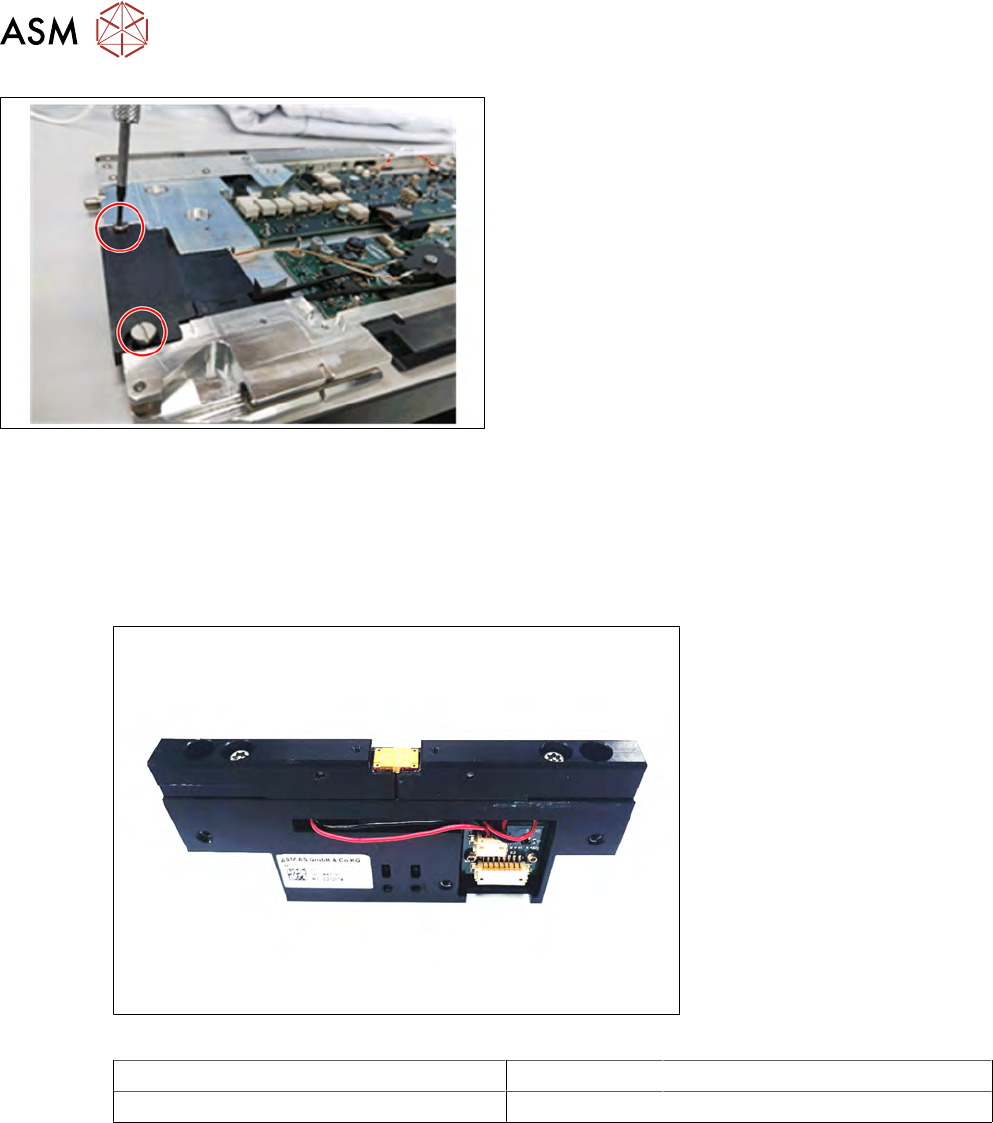
► Screw the EDIF into place using the two marked
screws (Collar screw D4x3.15 M3, 03050957-xx)
with 0.9Nm.
► Check whether the EDIF springs back to the front
if slight pressure is applied to it.
If the EDIF does not spring back, loosen the screws
and make sure that the two springs are aligned to-
wards the front and are not bent.
► Reassemble the left side plate (see section 2.4.2
"Fitting the side plate" [}16]).
2.6 Contact module
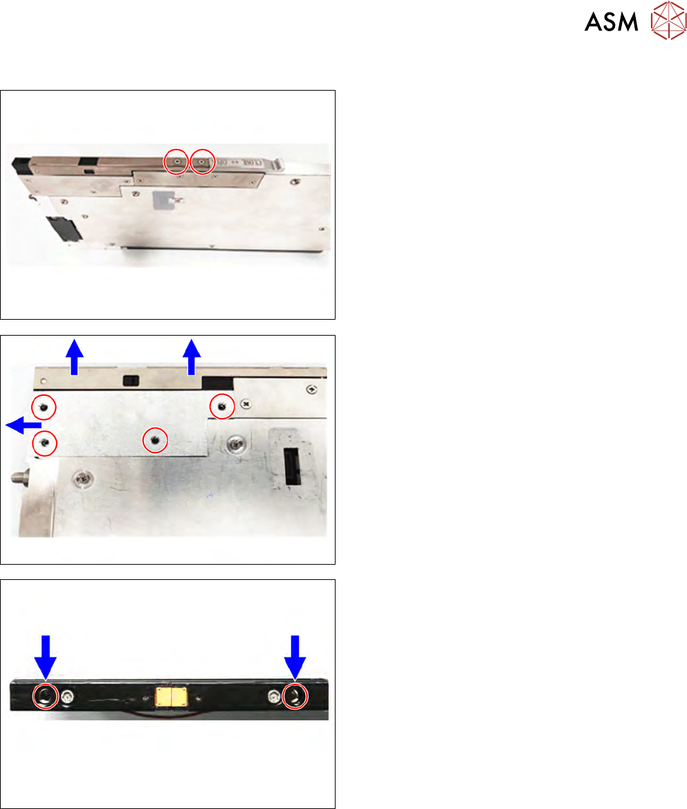
Required spare part
Fig.5: CRDL contact module
Feeder module Item no. Designation
MeasurementFeeder X 03148670-xx CRDL contact module
Required tools
●
Flat-bladed screwdriver
●
Phillips screwdriver
●
Allen key, size 2.5 mm
●
Allen key, size 3 mm
●
Loctite 243
2 Replacing spare parts
2.6 Contact module
Service Manual SIPLACE MeasurementFeeder X 02/2020 21
2.6.1 Removing the contact module
► Place the MeasurementFeeder onto a table.
► Loosen the two cross head countersunk screws
which are holding the contact module cover using
a 3mm Allen key.
► Remove the contact module cover in direction of
arrow.
► Loosen the four cross head countersunk screws
which are holding the protective plate using a
2.5mm Allen key.
► Remove the protective plate.
► Loosen the two Allen screws on the top of the
contact module using a 3mm Allen key.