DMM4020.pdf - 第9页
Digital Multimeters — T ektronix DMM4020 AC Current The following A C current speci fi cations are for sinusoidal signals with amplitudes greater than 5% of range. For inputs fro m 1% to 5% of range , add an additional er…
Datasheet
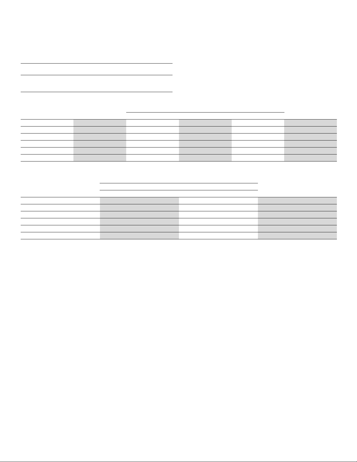
DC Current
Characteristic
Description
Input Protection
Tool-accessible 11 A / 1000 V and 440 mA / 1000 V
fuses
Shunt Resist
ance
0.01 Ω for 2 A a
nd 10 A ranges
1 Ω for 20 mA an
d200mA
Burden volta
ge <5 mV for 200 μA and 2 mA range
Input Characteristics
ResolutionRange
Full Scale
(5½ Digits)
Slow
Medium Fast
Burden Voltage
200 μA 199.999 μA0.001μA0.01μA0.01μA<5mV
2 mA 1999.99 μA0.01μA0.1μA0.1μA<5mV
20 mA 19.9999 mA 0.1 μA1μA1μA <0.05 V
200 mA 19.9999 mA 1 μA10μA10μA<0.5V
2 A 1.99999 A 10 μA100μA100μA<0.1V
10 A 10.0000 A 100 μA1mA 1mA<0.5V
Accuracy
Uncertainty*
3
90 days 1 year
Range
23 °C ±5 °C 23 °C ±5 °C
Te mp eratu re Coefficient/°C
Outside18-28°C
200 μA 0.02 + 0.005 0.03 + 0.005 0.003 + 0.001
2 mA 0.015 + 0.005 0.02 + 0.005 0.002 + 0.001
20 mA 0.03 + 0.02 0.04 + 0.02 0.005 + 0.001
200 mA 0.02 + 0.005 0.03 + 0.008 0.005 + 0.001
2 A 0.05 + 0.02 0.08 + 0.02 0.008 + 0.001
10 A 0.18 + 0.01 0.2 + 0.01 0.008 + 0.001
*
3
Uncertainty given as ±(% of reading + % of range).
8 www.tektronix.comdmm
Digital Multimeters — Tektronix DMM4020
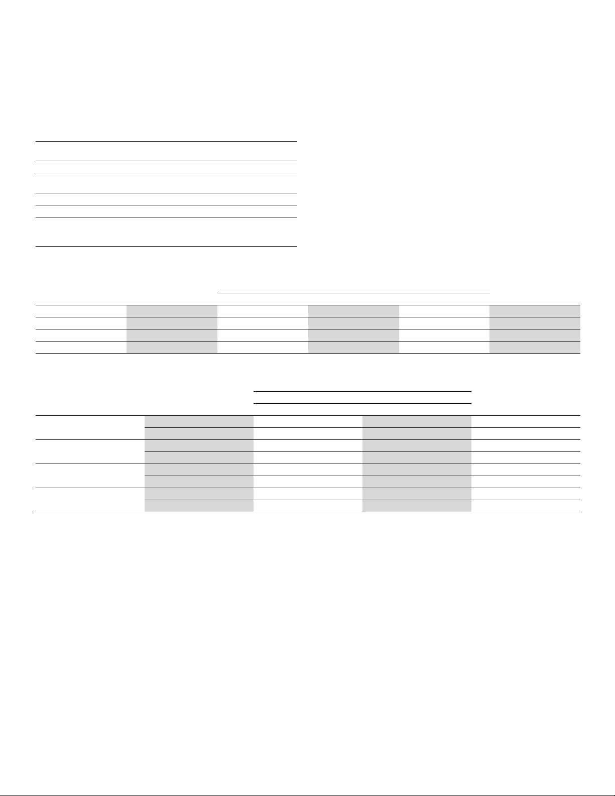
AC Current
The following A
C current specifications are for sinusoidal signals with amplitudes
greater than 5% of range. For inputs from 1% to 5% of range, add an additional
error of 0.1% of range.
Characteristic
Description
Input Protection
Tool-accessible 11 A / 1000 V and 440 mA / 1000 V
fuses
Measurement Method
AC-coupled true RMS
Shunt Resistance 0.01 Ω for 2 A and 10 A ranges
1 Ω for 20 mA and 200 mA
AC Filter Bandwidth
20 Hz - 100 kHz
Maximum C rest Factor 3:1 at Full Scale
Additional Crest Factor
Errors (<100 Hz)
Crest Factor 1-2, 0.05% of full scale
CrestFactor2-3,0.2%offullscale
Only applies to non-sinusoid signals
Input Characteristics
ResolutionRange
Full Scale
(5½ Digits)
Slow
Medium Fast
Burden Voltage
20 mA 19.9999 mA 0.1 μA1μA1μA <0.05 V
200 mA 199.999 mA 1 μA10μA10μA<0.5V
2 A 1.99999 A 10 μA100μA100μA<0.1V
10 A 10.0000 A 100 μA1mA 1mA<0.5V
Accuracy
Uncertainty*
3
90 d ays 1 year
Range Frequency
23 °C ± 5 °C 23 ° C ±5 °C
Temperature C oef ficien t/°C
Outside 18 - 28 °C
20 Hz - 45 Hz 1 + 0.05 1.25 + 0.06 0.015 + 0.00520 mA
45 Hz - 2 kHz 0.25 + 0.05 0.3 + 0.06 0.015 + 0.005
20 Hz - 45 Hz 0.8 + 0.05 1 + 0.06 0.015 + 0.005200 mA
45 Hz - 2 kHz 0.25 + 0.05 0.3 + 0.06 0.015 + 0.005
20 Hz - 45 Hz 1 + 0.05 1.25 + 0.06 0.015 + 0.0052A
45 Hz - 2 kHz 0.25 + 0.05 0.3 + 0.06 0.015 + 0.005
20 Hz - 45 Hz 1 + 0.1 1.25 + 0.12 0.015 + 0.00510 A
45 Hz - 2 kHz 1 + 0.1 0.5 + 0.12 0.015 + 0.005
*
3
Uncertainty given as ±(% of reading + % of range).
www.tektronix.comdmm 9
Datasheet
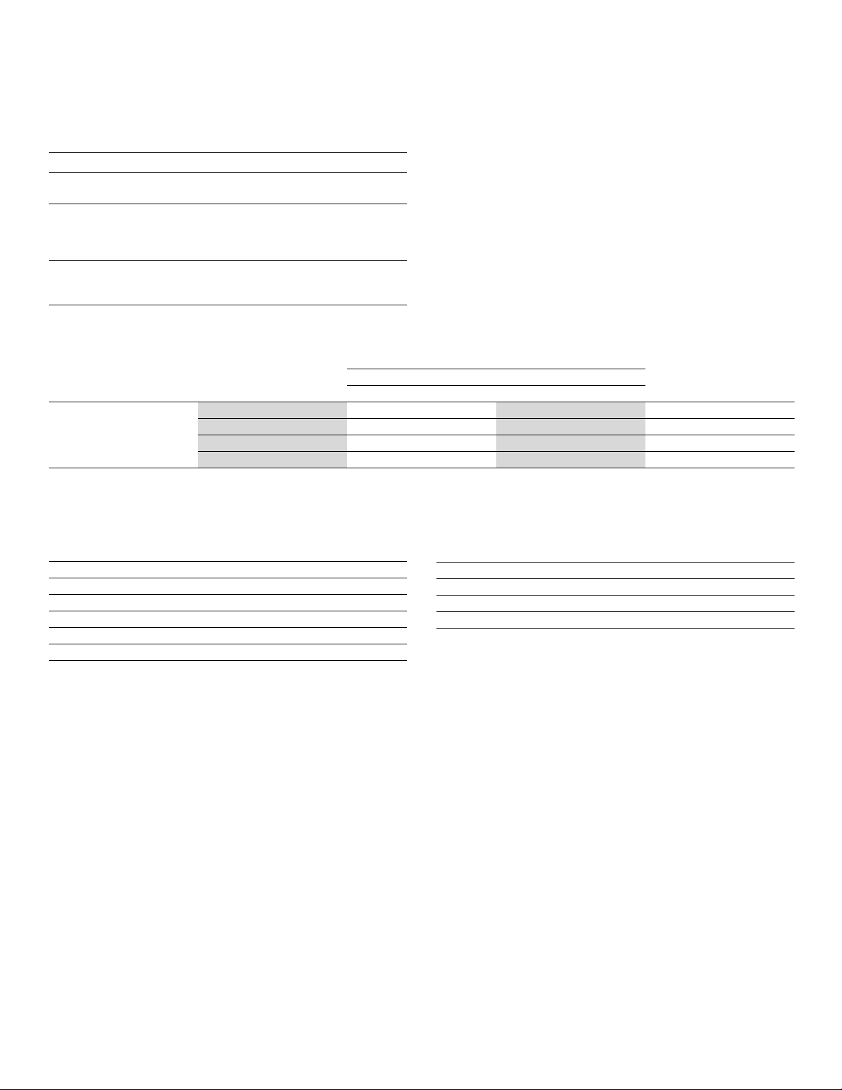
Frequency
Characteristic Description
Gate Time
131 ms
Measurement
Method
AC-coupled input using the AC voltage
measurement function
Settling
Considerations
When measuring frequency after a DC offset
voltage change, errors may occur. For the most
accurate measurement, wait up to 1 second to allow
input-blocking RC time constant to settle
Measurement
Considerations
To minimize measurement errors, shield inputs
from extern al noise when measuring low-voltage,
low-frequency signals
Input Characteristics
Uncertainty
90 d ays 1 year
Range Frequency
23 °C ± 5 °C 23 ° C ±5 °C
Temperature C oef ficien t/°C
Outside 18 - 28 °C
20 Hz - 2 kHz 0.01 + 0.002 0.01 + 0.003 0.002 + 0.001
2 kHz - 20 kHz 0.01 + 0.002 0.01 + 0.003 0.002 + 0.001
20 kHz - 200 kHz 0.01 + 0.002 0.01 + 0.003 0.002 + 0.001
100mVto750V*
4, 5
200 kHz - 1 MHz 0.01 + 0.004 0.01 + 0.006 0.002 + 0.002
*
4
Input >100 mV.
*
5
Limitedto8×10
7
VHz.
Continuity
Characteristic
Description
Continuity Threshold 20 Ω
Test Current
1mA
Response Time
100 S/s with audible tone
Rate Fast
Maximum Reading
199.99 Ω
Resolution
0.01 Ω
Diode Test
Characteristic
Description
Response Time
100 S/s with audible tone
Rate Fast
Maximum Reading 1.9999 V
Resolution 0.1 mV
10 www.tektronix.comdmm